Eureka AIR delivers breakthrough ideas for toughest innovation challenges, trusted by R&D personnel around the world.

Gas furnace for heating indoor space and controlling method thereof

Active Publication Date: 2017-06-22
LG ELECTRONICS INC
View PDF2 Cites 0 Cited by
  • Summary
  • Abstract
  • Description
  • Claims
  • Application Information

AI Technical Summary

Benefits of technology

This patent describes a gas furnace for indoor spaces that has several technical effects. First, it uses only one valve to make the fuel flow path compact and simple, reducing production costs. Second, it uses a controlling method to reduce the temperature difference in the indoor space by controlling heat power in three levels, using a thermostat that generates only two signals. Third, it economizes in production costs by minimizing the number of valves and simplifying the fuel flow path.

Problems solved by technology

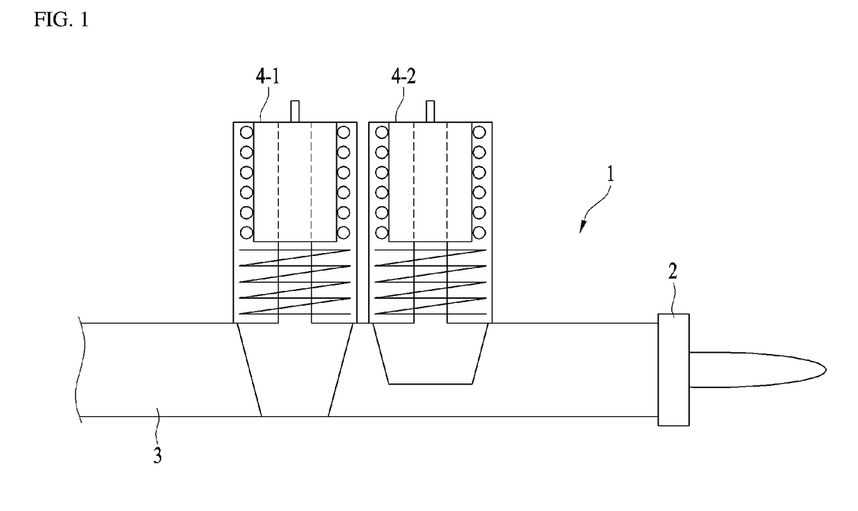
Meanwhile, the conventional gas furnace uses the thermostat generating the two signals and the two solenoid valves 4-1 and 4-2, so that it has a disadvantage of incapability of controlling the heat power of the burner 2 by three or more difference heat force (in other words, heating intensities).
In addition, the conventional gas furnace uses two or more solenoid valves 4-1 and 4-2 to control two or more heat powers and cannot help requiring the securing of the installation space for installing the plurality of the valves and having the complex flow path disadvantageously.
The conventional gas furnace is incapable of controlling the heat power linearly and has the complex flow path for the fuel supply, only to have a relatively high production cost.
Lastly, the conventional gas furnace is capable of controlling only the two steps of heat power based on the two signals transmitted from the thermostat, only to have a disadvantage of a large temperature difference in the indoor space.

Method used


Image

  • Gas furnace for heating indoor space and controlling method thereof
  • Gas furnace for heating indoor space and controlling method thereof
  • Gas furnace for heating indoor space and controlling method thereof

Examples


Embodiment Construction

[0051]Advantages and features of the present disclosure and methods for achieving the merits and characteristics will be more clearly understood from embodiments described in detail later in conjunction with the accompanying drawings. However, the present disclosure is not limited to the disclosed embodiments, but may be implemented in various different ways. The embodiments are provided to only complete the disclosure of the present disclosure and to allow a person having ordinary skill in the art to which the present disclosure pertains to completely understand the category of the invention. The present disclosure is only defined by the category of the claims. The same reference numbers are used to refer to the same or similar elements throughout the specification.

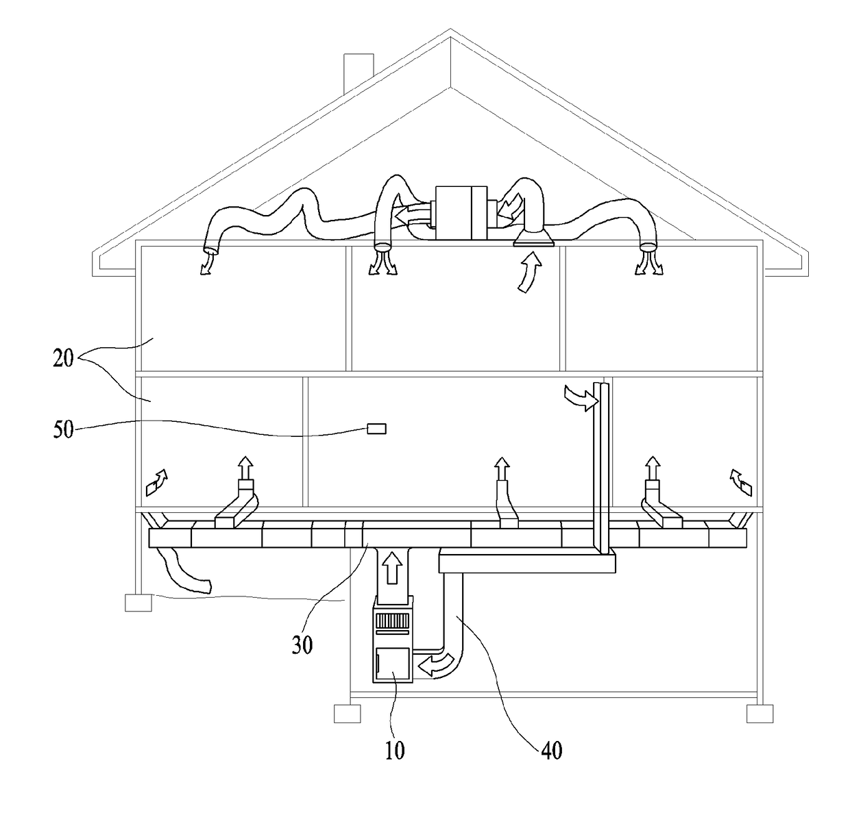
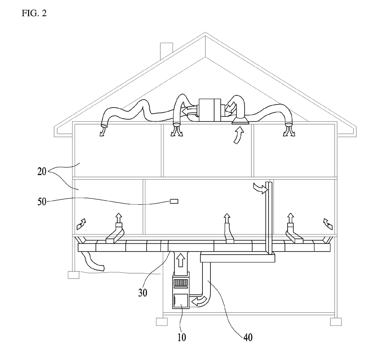
[0052]FIG. 2 is a schematic diagram illustrating a gas furnace in accordance with an embodiment of the present disclosure that is applied to an indoor space as a heating object space. With reference to FIG. 2, a gas furn...


PUM


Abstract

A gas furnace for heating an indoor space including a burner forming high-temperature exhaust gas by combusting fuel; an exhaust path in which the exhaust gas flows; a blower for suctioning internal air via a suction path; a supply path for guiding the internal air exhausted by the blower toward the indoor space, after heat-exchanged with the exhaust path; a valve of which an opening degree is controllable so as to supply a predetermined heat-power-based amount of fuel to the burner; and a controller controlling the opening degree of the valve based on a signal transmitted from a thermostat installed in the indoor space, wherein the heat power of the burner is controlled in different heat power levels based on the opening degree of the valve, and a controlling method of the gas furnace for heating the indoor space.

Description

[0001]Pursuant to 35 U.S.C. §119(a), this application claims the benefit of earlier filing date and right of priority to Korean Application No. 10-2015-0183892, filed on Dec. 22, 2015, the contents of which are hereby incorporated by reference herein in their entirety.BACKGROUND OF THE DISCLOSURE[0002]Field of the Disclosure[0003]The disclosure relates to a gas furnace that heats an indoor space by supplying warm air via heat exchange between internal air and hot exhaustion gas generated by combustion of fuel, and a controlling method thereof. More particularly, the disclosure relates to a gas furnace for heating an indoor space including one valve of which a heating power is controllable by multi-steps, and a controlling method thereof.[0004]Discussion of the Related Art[0005]In general, a gas furnace is a device used for heating an indoor space.[0006]A gas furnace generally includes a burner for fuel combustion. The gas furnace provides heat by adjusting the amount of the fuels su...

Claims


Application Information

Patent Timeline
IPC IPC(8): F24D19/10
CPCF24D19/1084F24H15/281F24H15/254F24H15/36F24H15/305F24H15/345
Inventor PARK, JANGHEEJEONG, YONGKICHUNG, BAIKYOUNG
Owner LG ELECTRONICS INC
Why Eureka
Eureka Blog
Learn More