Battery element having a thermal conduction element

A technology of battery components and battery cells, applied in battery pack components, batteries, electrical components, etc.

Active Publication Date: 2020-07-24
ERBSLOH ALUMINUM
View PDF15 Cites 0 Cited by
  • Summary
  • Abstract
  • Description
  • Claims
  • Application Information

AI Technical Summary

Problems solved by technology

Disadvantage is the multilayer

Method used


Image

  • Battery element having a thermal conduction element
  • Battery element having a thermal conduction element
  • Battery element having a thermal conduction element

Examples


Embodiment Construction

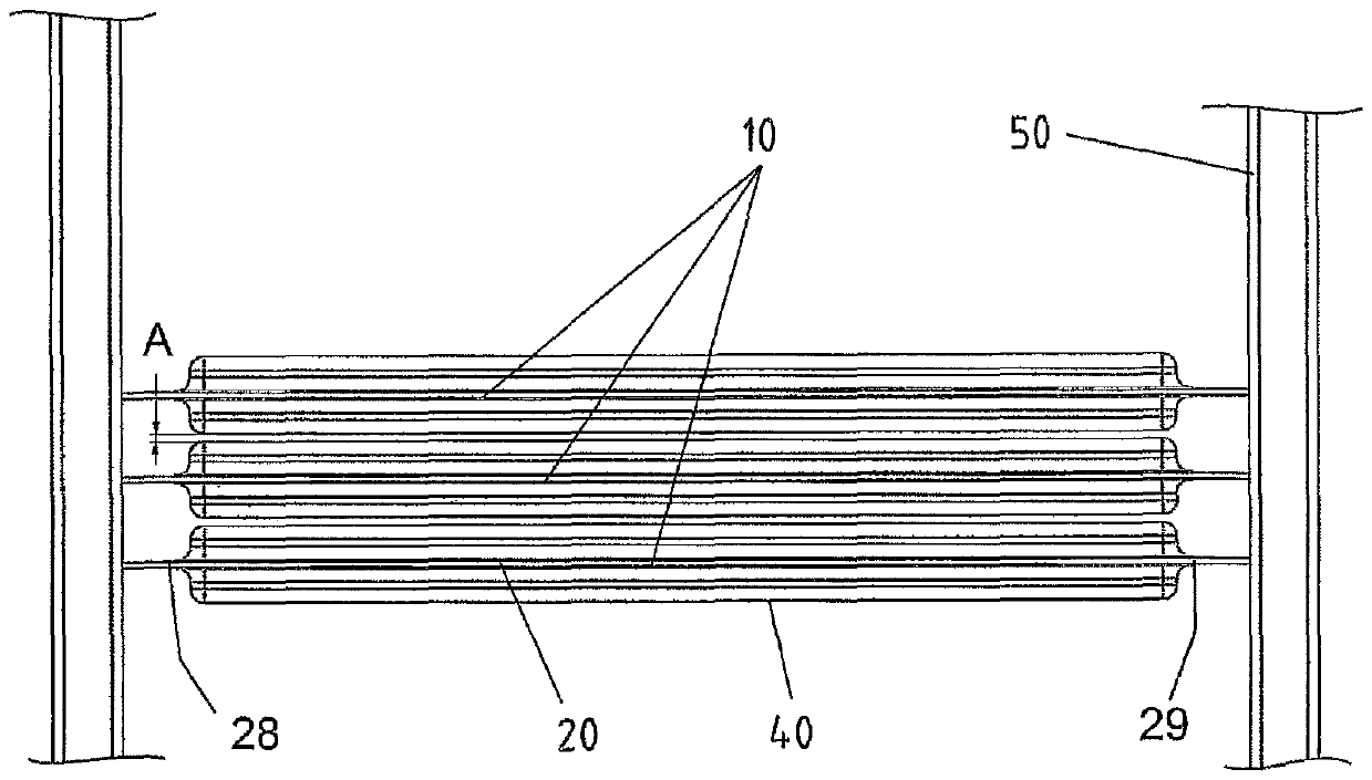
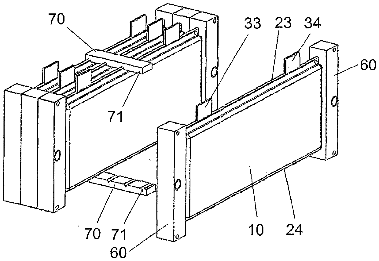
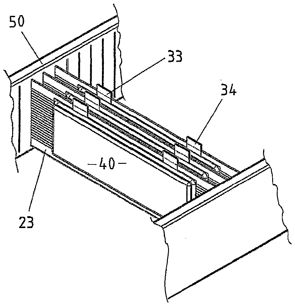
[0039] figure 1 The new battery element 10 shown comprises two electrode stacks 30 , 30 ′, which are arranged on both sides of a heat-conducting element provided for temperature control. The heat conducting element is a flat multi-chamber hollow profile 20 . The electrode stacks 30 , 30 ′ are only shown abstractly. They comprise electrodes 31 which are arranged to be folded into active layers together with the electrolyte and which are present separated from one another by a separator 32 . The electrode stack 30 , 30 ′ is surrounded on the outside by an outer sheath 40 or 40 ′. In contrast to known pouch-shaped cells in which the electrode stacks are likewise surrounded by an outer casing, the new battery element 10 includes two electrode stacks and additionally includes a centrally arranged multi-chamber hollow profile 20 as an integral component. Such a multi-chamber hollow profile has a plurality of chambers 21 arranged next to one another and running in parallel. On th...


PUM

PropertyMeasurementUnit
Heightaaaaaaaaaa

Abstract

The invention relates to a new battery element (10), in which a thermal conduction element in the form of a multi-chamber hollow profiled element (20) having chambers (21) is integrated in addition toa battery cell. The heat transfer is optimal, because the temperature-controlled multi-chamber hollow profiled element (20) is in planar contact with the battery cell. The electrodes (31) of the battery element (10) are surrounded by an outer electrical insulation, which is formed solely by an outer film (40, 40') or by said film (40, 40') and a thermoplastic plastic coating (27) of the multi-chamber hollow profiled element (20).

Description

technical field [0001] The invention relates to a battery element having at least one electrode stack and at least one heat-conducting element, the electrode stack being surrounded by an outer electrically insulating structure. Background technique [0002] Battery cells are known, in particular lithium-ion cells, pouch cells, which are considered to be advantageous cell types for use in motor vehicles on the basis of their high energy density and their low weight. Such a battery cell comprises stacked or folded electrochemically active layers which are separated from one another by separators in the form of plastic nonwovens in order to prevent short circuits. These electrode stacks are surrounded by a flexible outer membrane. These outer membranes are closed except at the edges and the membrane pockets thus formed are filled with an organic electrolyte. The film pocket is then closed and sealed, wherein the contact strips protrude from the film pocket as connections for ...

Claims


Application Information

Patent Timeline
IPC IPC(8): H01M2/02H01M2/08H01M10/653H01M10/647H01M10/6557H01M10/625H01M2/10H01M10/0585H01M10/60H01M50/119H01M50/121H01M50/122H01M50/126H01M50/211
CPCH01M2220/20H01M10/625H01M10/647H01M10/6557H01M10/654Y02E60/10Y02P70/50H01M50/126H01M50/121H01M50/211H01M50/119H01M50/122H01M50/20H01M10/613H01M10/653H01M50/169H01M50/538H01M10/655
Inventor N.W.苏克L.莱赫特A.贝克M.格茨
Owner ERBSLOH ALUMINUM
Why Eureka
Try Eureka