
Ceiling type indoor unit of air conditioner

a technology of indoor unit and control method, which is applied in the direction of lighting and heating apparatus, space heating and ventilation control system, heating type, etc., to achieve the effect of minimizing a temperature differen

Active Publication Date: 2020-06-18
LG ELECTRONICS INC
View PDF0 Cites 0 Cited by
  • Summary
  • Abstract
  • Description
  • Claims
  • Application Information

AI Technical Summary

Benefits of technology

The present invention provides a control method for a ceiling-mounted air conditioner that is designed to minimize temperature differences between the floor and indoor air, and to reduce the temperature difference between the upper and lower sides of a room. Additionally, the invention utilizes a vision sensor to identify the position of an occupant, and adjusts the air conditioner to minimize the temperature difference between the upper and lower sides of the space where the occupant is located. These methods of control allow for more efficient and effective air conditioning, leading to improved comfort for the occupants of a room.

Problems solved by technology

In the related art, during heating, there is a problem that the ceiling-type indoor unit provides only an airflow control according to an indoor temperature and a target temperature and a floor temperature in a room is not considered.

Method used


Image

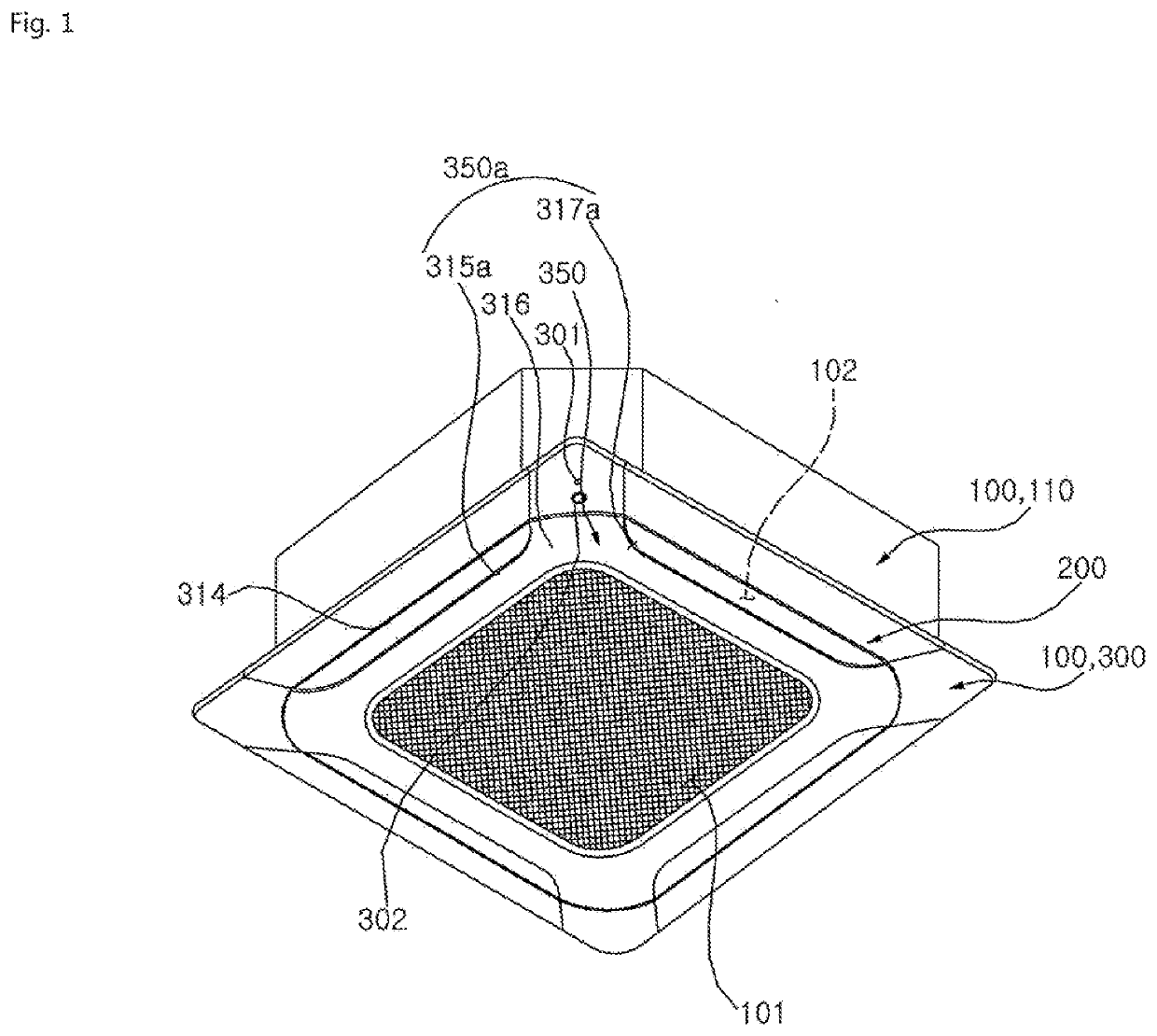
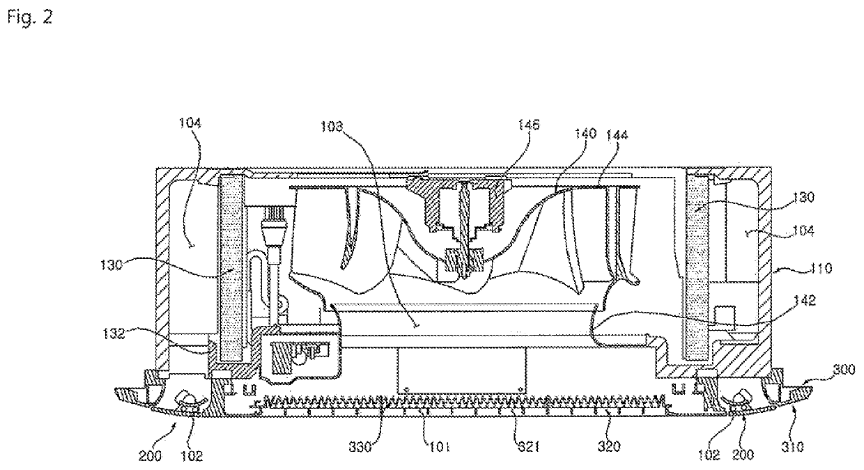
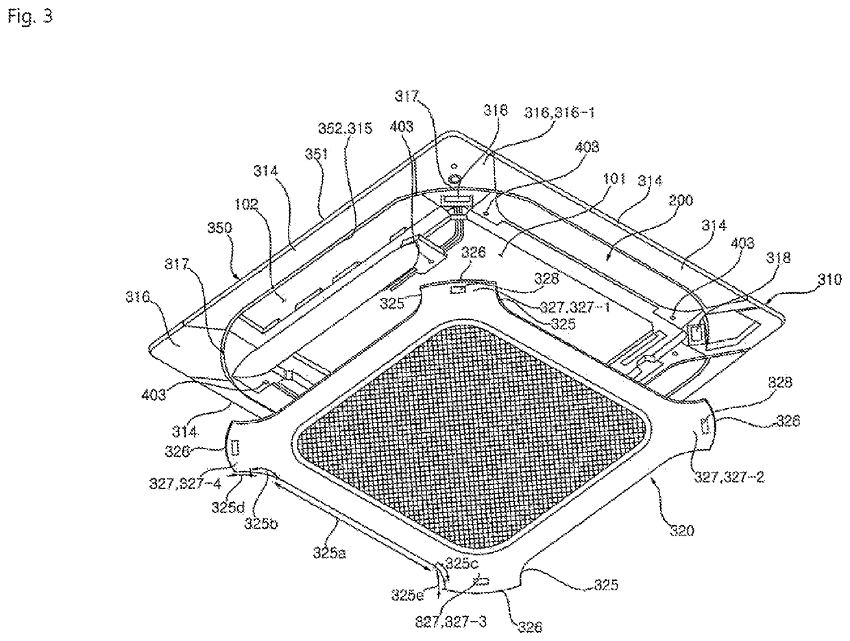
  • Ceiling type indoor unit of air conditioner
  • Ceiling type indoor unit of air conditioner
  • Ceiling type indoor unit of air conditioner

Examples


second embodiment

[0721]FIG. 24 is a flowchart showing a control method during heating according to the present disclosure.

[0722]In the control method of a ceiling type indoor unit according to the second embodiment, whether or not the room is heated is determined according to the temperature difference between the room temperature Tp and the set temperature Ts, and even when there is little or no heating load due to the temperature difference between the room temperature Tp and the set temperature Ts, the temperature between the room temperature Tp and the floor temperature Tb is determined to perform the floor heating.

[0723]Accordingly, in a case where it is determined that there is a heating load due to the temperature difference between the room temperature Tp and the set temperature Ts, the room is heated.

[0724]Even when it is determined that there is little or no heating load due to the temperature difference between the room temperature Tp and the set temperature Ts, the floor heating load is ...

first embodiment

[0730]Since the rest of the configuration is the same as that of the first embodiment, detailed description thereof will be omitted.

third embodiment

[0731]FIG. 25 is a flowchart showing a control method during heating according to the present disclosure.

[0732]In the control method of a ceiling type indoor unit according to the present embodiment, it is determined whether or not the room is heated according to the temperature difference between the room temperature Tp and the set temperature Ts, and even when there is little or no heating load due to the temperature difference between the room temperature Tp and the set temperature Ts, the floor heating load is determined according to the temperature difference between the room temperature Tp and the floor temperature Tb.

[0733]In a case where it is determined that there is the heating load according to the temperature difference between the room temperature Tp and the set temperature Ts, the room is heated.

[0734]Thereafter, even when it is determined that there is little or no heating load according to the temperature difference between the room temperature Tp and the set tempera...


PUM


Abstract

According to the present disclosure, it is determined whether or not the room is heated according to a temperature difference between a room temperature Tp and a set temperature Ts, and even when there is little or no heating load due to the temperature difference between the room temperature Tp and the set temperature Ts, the floor heating is performed by determining a temperature difference between the room temperature Tp and a floor temperature Tb.

Description

BACKGROUND OF THE INVENTIONField of the Invention[0001]The present disclosure relates to a control method of a ceiling type indoor unit of an air conditioner, and more particularly, to a control method of a ceiling type indoor unit according to a floor temperature in a room.Related Art[0002]In general, an air conditioner includes a compressor, a condenser, an evaporator, and an expander, and uses an air conditioning cycle to supply cold air or warm air to a building or a room.[0003]The air conditioner is structurally divided into a separate type air conditioner in which the compressor is disposed outdoors and an integrated type air conditioner in which the compressor is integrally manufactured.[0004]In the separate type air conditioner, an indoor heat exchanger is installed in an indoor unit, an outdoor heat exchanger and a compressor are installed in an outdoor unit, and two separated units are connected to by a refrigerant pipe.[0005]In the integrated type air conditioner, an indo...

Claims


Application Information

Patent Timeline
Patent Type & Authority Applications(United States)
IPC IPC(8): F24F11/00F24F1/0317
CPCF24F11/0001F24F1/0317F24F2013/0616F24F1/0047F24F1/0014F24F11/79
Inventor LEE, JUYOUNCHOI, JAEHEUK
Owner LG ELECTRONICS INC
Learn More