Valve timing adjusting apparatus

a timing adjustment and valve technology, applied in mechanical equipment, valve arrangements, machines/engines, etc., can solve the problems of increased sleeve size, complex configuration, and inability to adjust the axial hole length,

Inactive Publication Date: 2009-06-11
DENSO CORP
View PDF5 Cites 53 Cited by
  • Summary
  • Abstract
  • Description
  • Claims
  • Application Information

AI Technical Summary

Problems solved by technology

However, in the apparatus of JP-A-2004-340142, a length of the axial hole, which is provided to the vane rotor, is inevitably restricted by a specification of the apparatus, such as a thickness of the vane rotor.
As a result, a length of the sleeve that is coaxially received in the axial hole is restricted.
The above restriction or limitation may be a bottleneck disadvantageously in the attempt to secure a length of a sealing part for sealing between slide boundary surfaces of the sleeve and the spool in order to improve control responsivity of control valve and to adjust responsivity of valve timing.
The first and second drain ports are required to be communicated with the end portion of the camshaft, and thereby the sleeve may be increased in size and may have a complex configuration.

Method used


Image

  • Valve timing adjusting apparatus
  • Valve timing adjusting apparatus
  • Valve timing adjusting apparatus

Examples


first embodiment

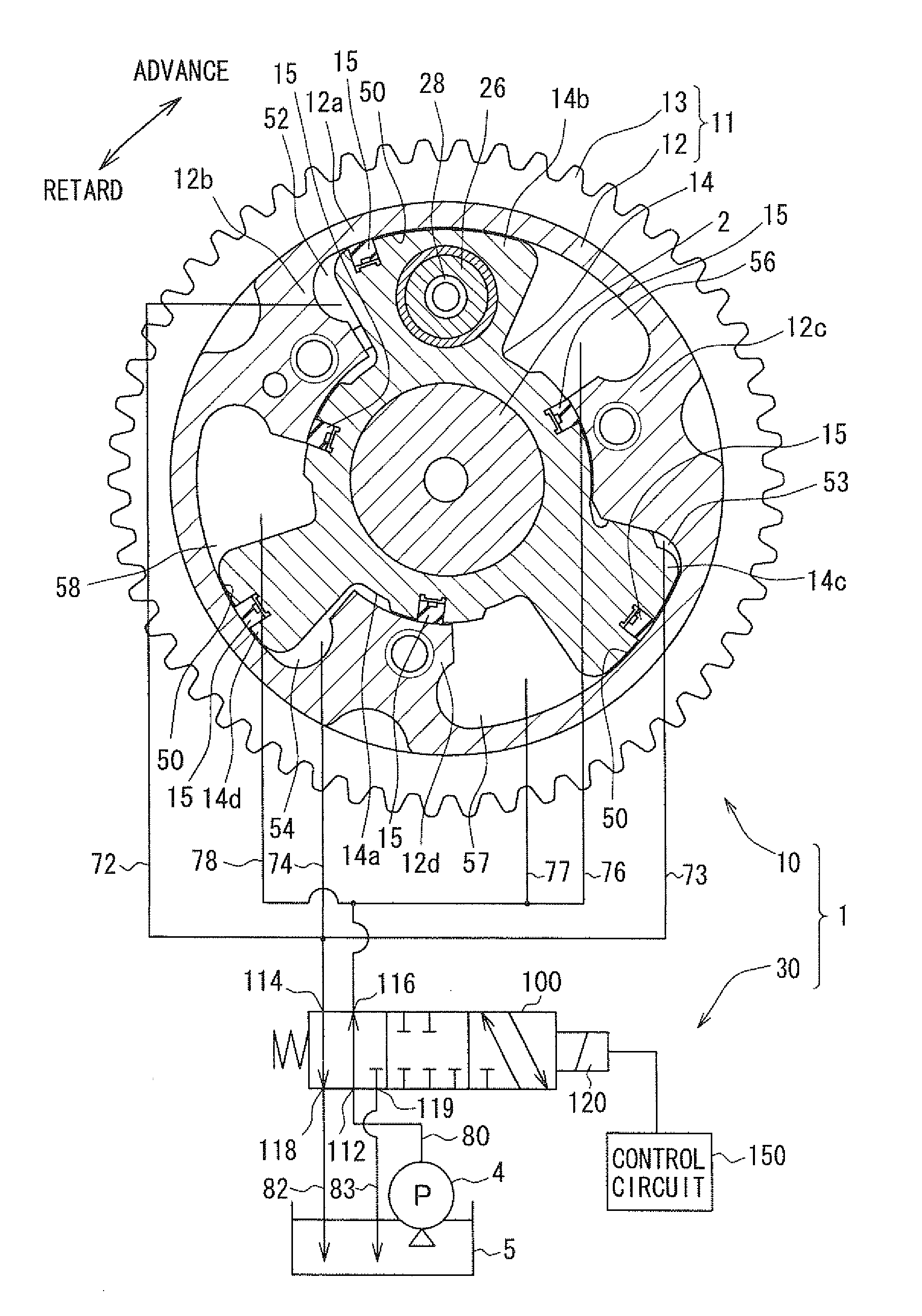
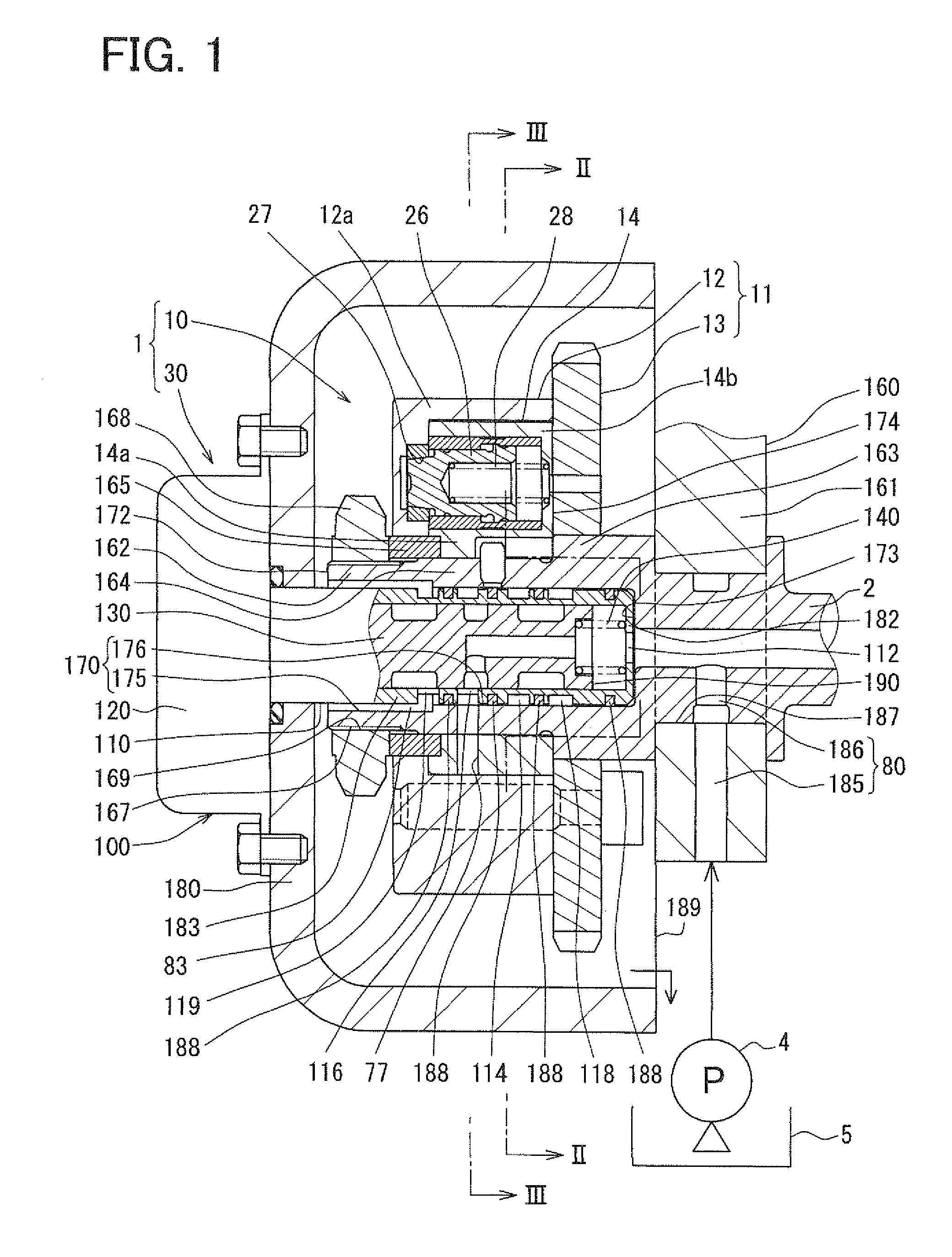
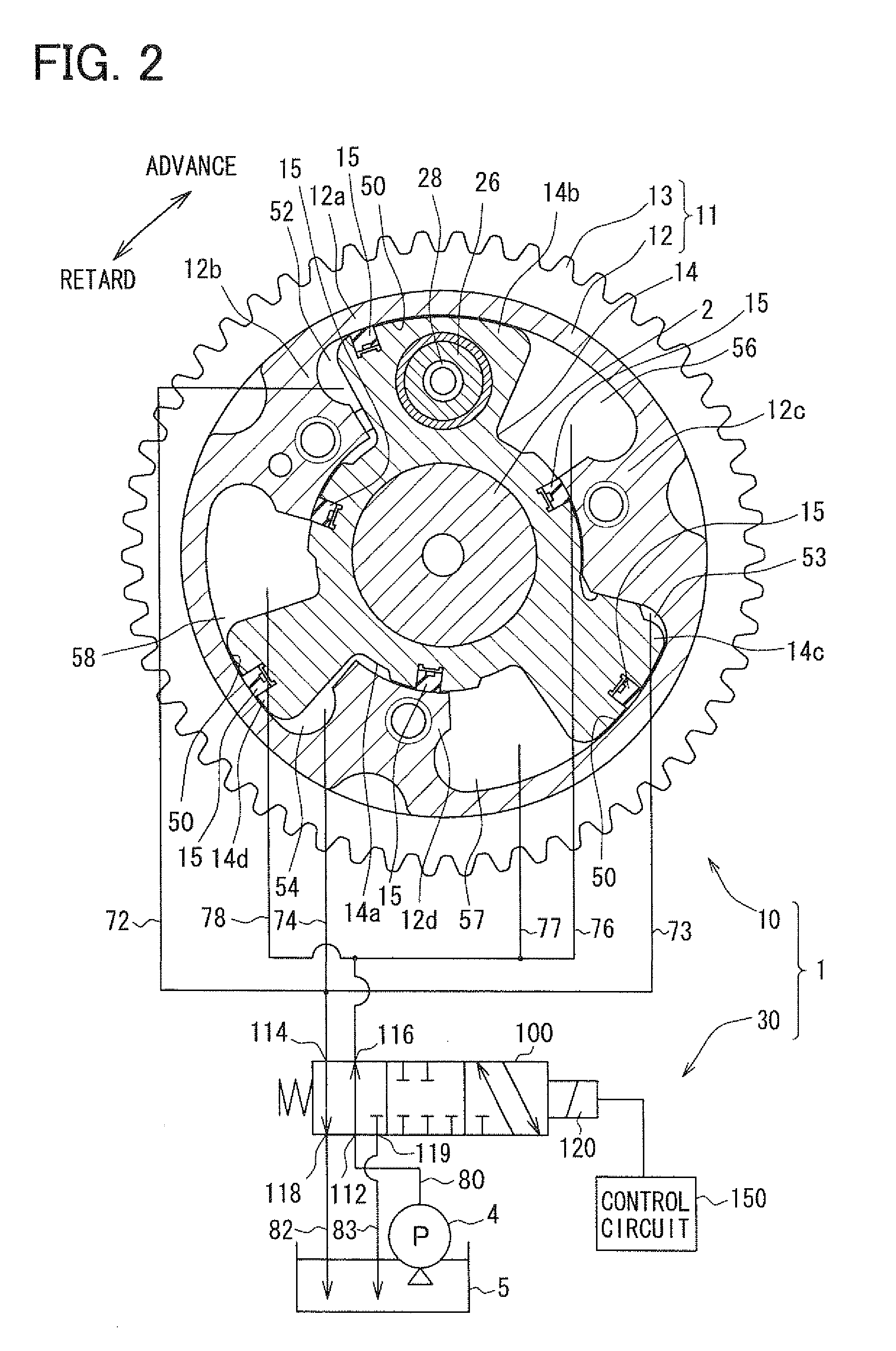
[0024]FIGS. 1, 2, 9 show examples, in which a valve timing adjusting apparatus 1 of the first embodiment of the present invention is applied to an internal combustion engine of a vehicle. The valve timing adjusting apparatus 1 is a fluid operated apparatus that employs hydraulic oil serving as “working fluid”, and is capable of adjusting valve timing of an intake valve that serves as a “valve”.

(Basic Configuration)

[0025]A basic configuration of the present embodiment will be described. The valve timing adjusting apparatus 1 includes a drive unit 10 and a control unit 30. The drive unit 10 is provided in a driving force transmission system and is driven by hydraulic oil. The driving force transmission system transmits a driving force of a crankshaft (not shown) of an internal combustion engine to a camshaft 2 of the internal combustion engine. The control unit 30 controls supply of hydraulic oil to the drive unit 10.

(Drive Portion)

[0026]The drive unit 10 includes a housing 11 and a v...

second embodiment

[0085]As shown in FIG. 10, the second embodiment of the present invention is a modification of the first embodiment. The second embodiment is characterized in that a check valve 200 is provided in the inner passage 197 of the spool 130.

[0086]Specifically, the check valve 200 includes a valve seat 202, a valve member 204 and a biasing member 206. The valve seat 202 is a radially inner surface formed on an intermediate position of the inner passage 197, and an inner diameter of the valve seat 202 is reduced toward the input port 112 to have a conic surface. The valve member 204 is made of a metal to have a bulbous shape, and is provided in the inner passage 197 on an opposite side of the valve seat 202 opposite from the input port 112. Thus, the valve member 204 is able to be displaceable in the longitudinal direction so that the valve member 204 is positioned away from and is seated on the valve seat 202. The biasing member 206 is made of a metallic compression coil spring, and is pr...


PUM


Abstract

A valve timing adjusting apparatus for an internal combustion engine having a bearing includes a camshaft, a housing, a vane rotor, a control valve, and a fastening member. The fastening member is mounted on an axial end portion of the camshaft on a side of the vane rotor opposite from the bearing. The vane rotor is coaxially fastened to the camshaft between the fastening member and a step portion, which is provided to the camshaft on a side of the bearing. A sleeve of the control valve is coaxially received in an axial hole of the camshaft, which opens at an end surface of the end portion of the camshaft. Each of the advance output port and the retard output port is communicated with a corresponding one of the advance chamber and the retard chamber through the camshaft.

Description

CROSS REFERENCE TO RELATED APPLICATION[0001]This application is based on and incorporates herein by reference Japanese Patent Application No. 2007-315175 filed on Dec. 5, 2007.BACKGROUND OF THE INVENTION[0002]1. Field of the Invention[0003]The present invention relates to a valve timing adjusting apparatus that adjusts valve timing of a valve that is opened and closed by a camshaft driven by a torque transmitted from a crankshaft in an internal combustion engine.[0004]2. Description of Related Art[0005]Conventionally, a widely-used fluid driven valve timing adjusting apparatus includes a housing, which is rotatable with a crankshaft, and a vane rotor, which is rotatable with a camshaft. In general, in the above valve timing adjusting apparatus, the vane rotor defines an advance chamber and a retard chamber in the housing, and working fluid is supplied to the above advance chamber or the retard chamber to rotate the vane rotor relative to the housing in an advance direction or in a r...

Claims


Application Information

Patent Timeline
Patent Type & Authority Applications(United States)
IPC IPC(8): F01L1/344
CPCF01L1/3442F01L2001/34426F01L2001/34479F01L2001/34453F01L2001/34469F01L2001/34433
Inventor USHIDA, MASAYASU
Owner DENSO CORP
Why Eureka
Try Eureka