Mail processing tracking system and method

Active Publication Date: 2009-06-11
KÖRBER SUPPLY CHAIN LLC
View PDF32 Cites 30 Cited by
  • Summary
  • Abstract
  • Description
  • Claims
  • Application Information

AI Technical Summary

Benefits of technology

[0010]According to one embodiment of the invention it is assumed that the interior space of a postal facility is divided into zones, and that it is necessary for a cart or postal vehicle carrying mail trays to pass through a gateway to get from one zone to another. A zone or “tracking zone” is an area of a facility which has at least one RFID detection gateway through which a cart or container with one or more RFID tags must pass in order to enter

Problems solved by technology

In practice, this approach is problematic.
After first processing, the manifest of mail sorted to a specific pocket is broken, i.e, sweeping loses definite association between mail and tray, so it cannot be known which of several successive trays a specific mail piece was placed in.
Operator correlation of tagged tray and the letters it contains is unreliable and highly labor intense.
In another known approach, each mail piece is tagged with its own RFID tag, but this requires too many tags to be cost effective, and when tags are too clos

Method used


Image

  • Mail processing tracking system and method
  • Mail processing tracking system and method
  • Mail processing tracking system and method

Examples


Example

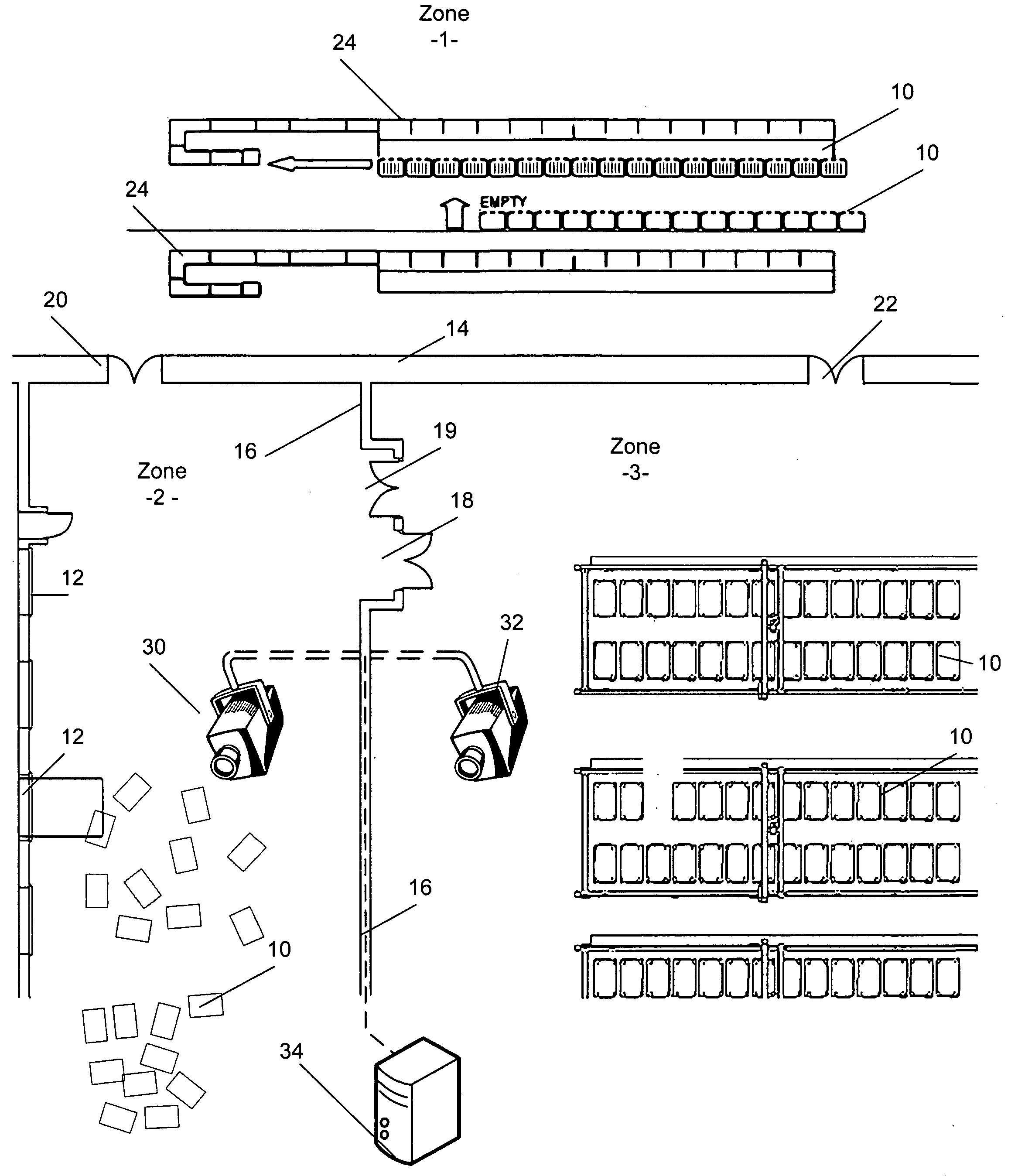
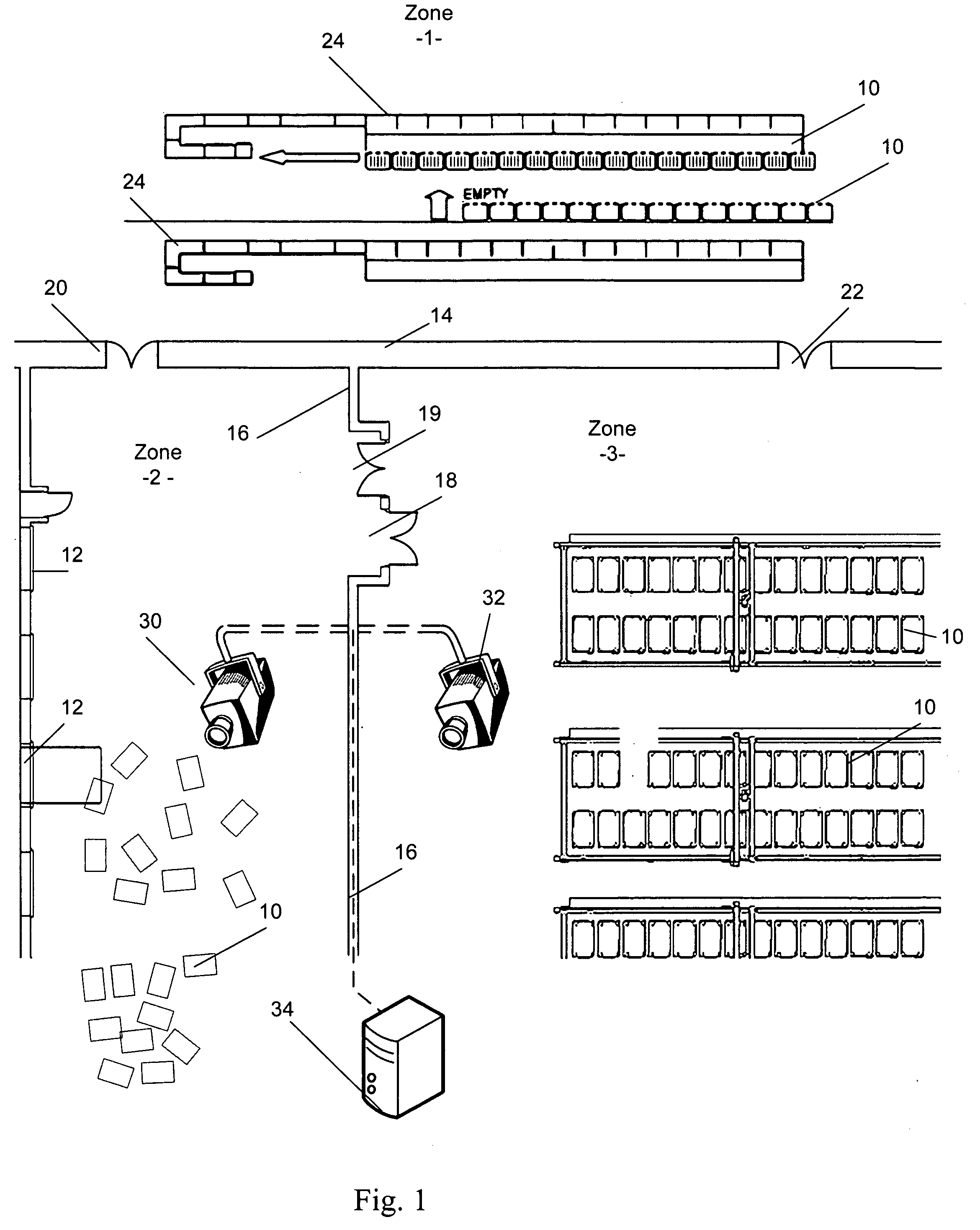
[0019]Referring to FIG. 1, in a postal facility according to the invention, an tracking system is in place wherein RFID tags are being used to track mail pieces and / or mail transport carts or vehicles 10, and visual tracking is used to track cart positions as they are transported through predefined zones.

[0020]In the example of FIG. 1, zone 1 is an area wherein DBCS sorting machines operate. Zone 2 is a loading zone adjacent a series of loading docks 12. Zone 3 is an optional holding area in which loaded carts 10 are parked for storage and later retrieval. Zone 1 is separated from zones 2 and 3 by a partition wall, fence or barrier 14. Similarly, a wall, fence or barrier 16 separates zones 2 and 3. Wall 16 has an RFID gate 18 that reads the tags on carts 10 moving from zone 3 to zone 2. An optional exit gate 19 not equipped for RFID detection may be provided for return of empty carts. Wall 14 is shown with a pair of RFID gates 20 and 22, which lead to zones 2 and 3 respectively.

[002...


PUM


Abstract

A method is described for tracking position of a mail piece within a facility. It includes steps of scanning a series of mail pieces to obtain identifying indicia therefrom, sorting the series of mail pieces according to a destination-based postal sorting strategy; and placing the sorted mail pieces into a container together with a marker comprising an RFID tag. In a computerized control system, identifiers for the RFID marker are identified with a sequence of mail pieces in the container. The RFID tag is scanned to associate a position of the container at the time of scanning with the mail in the container. The container is then transported, e.g. by loading a tray as the container onto a cart and then moving the cart. The method further includes video tracking the container from the position at the time of scanning to a later, different position at which a further postal operation takes place, such as loading of the trays onto a truck or feeding the mail from the trays onto the feeding ledge of a sorting machine hen a subsequent sorting step is needed.

Description

[0001]This application claims priority of U.S. provisional application No. 60 / 992,524 filed Dec. 5, 2007.FIELD OF THE INVENTION[0002]The invention relates to mail tracking systems for use in a postal sorting facility as currently operated by the U.S. Postal Service (USPS).BACKGROUND OF THE INVENTION[0003]Recently a number of proposals have been made to make use of RFID (radiofrequency ID) tags to track mail in postal processing. In the conventional approach to RFID tracking in mail processing, mail is sorted on an automated mail sorting machine such as an DBCS or MLOCR machine in use by the U.S. Postal Service. Such mail is swept from pockets of the sorter into trays by postal employees. Each tray has an RFID tag. In practice, this approach is problematic. After first processing, the manifest of mail sorted to a specific pocket is broken, i.e, sweeping loses definite association between mail and tray, so it cannot be known which of several successive trays a specific mail piece was ...

Claims


Application Information

Patent Timeline
IPC IPC(8): G06F19/00
CPCB07C3/00G07B17/00661G07B2017/00709G07B2017/00629G07B2017/0004
Inventor CARPENTER, MICHAEL D.
Owner KÖRBER SUPPLY CHAIN LLC
Why Eureka
Try Eureka