
Sensor device structure

a sensor device and structure technology, applied in the direction of measurement devices, measurement apparatus components, instruments, etc., can solve the problems of reducing the appeal of the device's outlook, ruining the interior decoration of the room, and even more troublesome jobs, so as to achieve the effect of minimal impact on the appeal of the sensor device's outlook and easy access and replacemen

Inactive Publication Date: 2009-06-18
GRAND MATE
View PDF4 Cites 4 Cited by
  • Summary
  • Abstract
  • Description
  • Claims
  • Application Information

AI Technical Summary

Benefits of technology

[0006]According to the present invention, a sensor is housed inside a casing of the sensor device. The casing has a reliably positioned yet manually removable cap so that, once the cap is removed, the sensor can be easily accessed and replaced. The cap is integrated with the casing smoothly so that the appealing of the outlook of the sensor device is minimally affected.

Problems solved by technology

Moreover, the sensor devices are usually installed on the ceiling or other difficult-to-reach location, thereby making the job even more troublesome.
However, this approach would reduce the appealing of the device's outlook or ruin the room's interior decoration.

Method used


Image

  • Sensor device structure
  • Sensor device structure
  • Sensor device structure

Examples


Embodiment Construction

[0015]The following descriptions are exemplary embodiments only, and are not intended to limit the scope, applicability or configuration of the invention in any way. Rather, the following description provides a convenient illustration for implementing exemplary embodiments of the invention. Various changes to the described embodiments may be made in the function and arrangement of the elements described without departing from the scope of the invention as set forth in the appended claims.

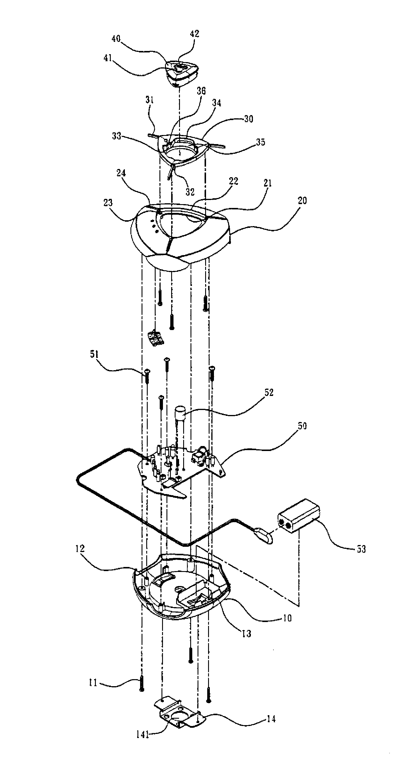
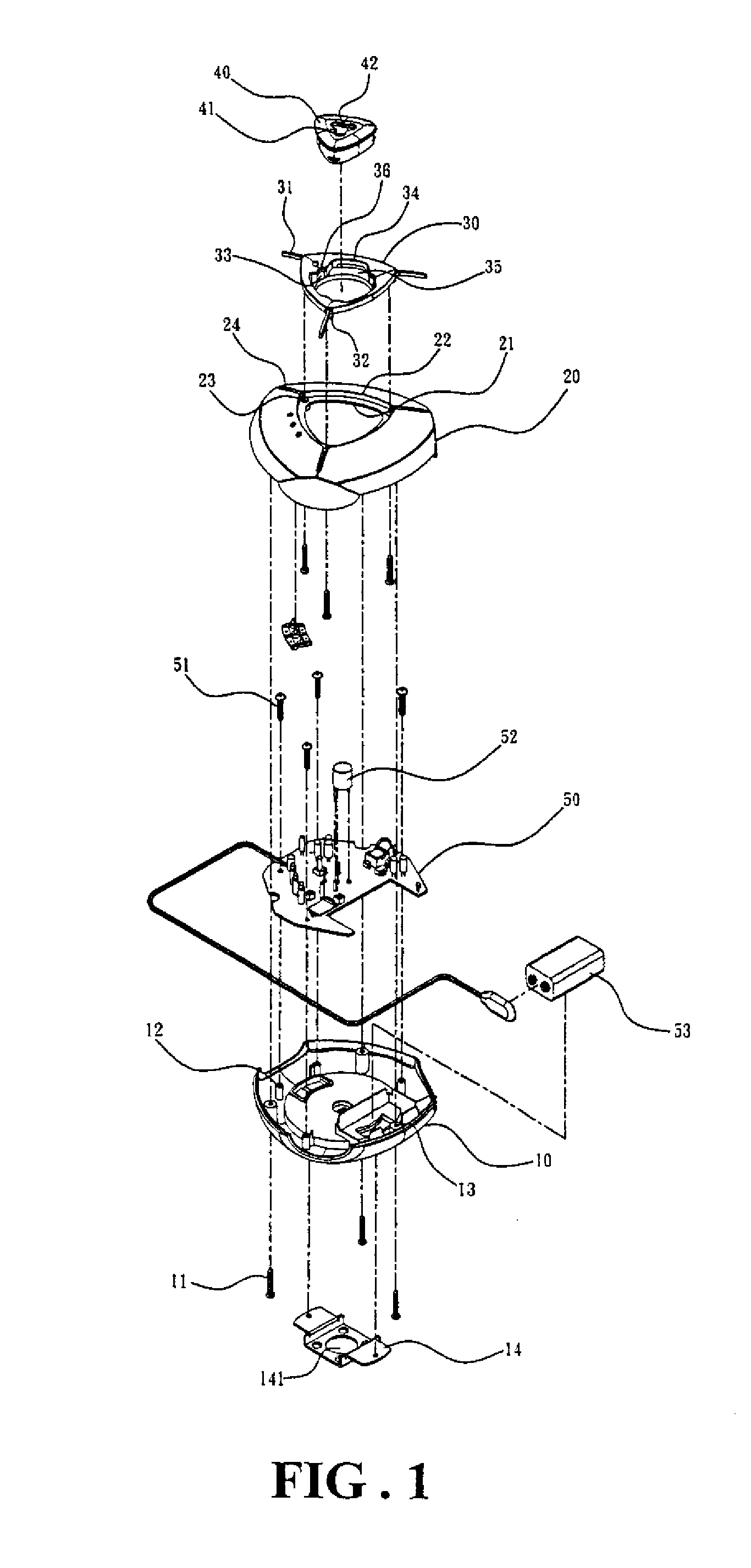
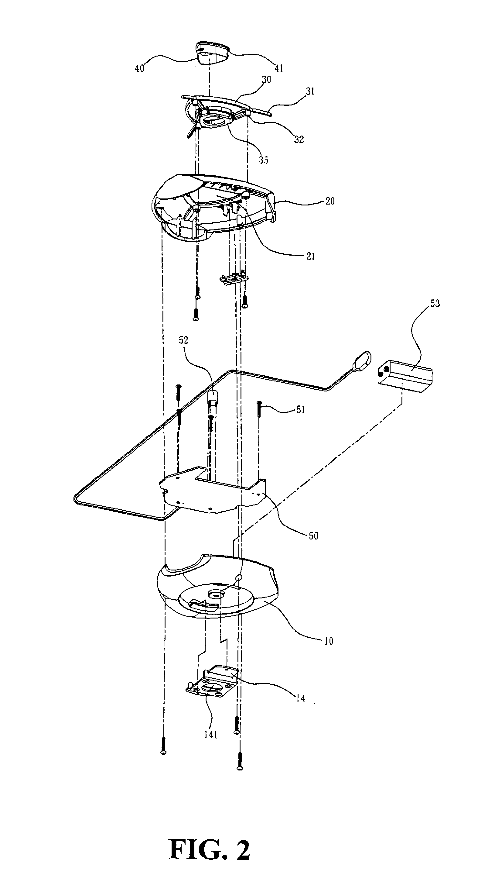
[0016]A sensor device according to an embodiment of the present invention, as shown in FIGS. 1 to 3, has a hollow casing formed by joining a first cover 10 to a second cover 20 with a number of bolts 11. A mounting piece 14 with a plug hole 141 is attached to an outside surface of the first cover 10 through which the sensor device could be fixed to a ceiling or a wall. The first cover 10 further has a battery chamber 13 inside and a number of bolt rods 12 are extended from inside the first cover 10 ...


PUM


Abstract

The sensor device has a casing housing a circuit board and a replaceable sensor on the circuit board. The casing has an opening corresponding to the sensor location and a manually removable cap is reliably positioned in the opening. Once the cap is removed, the sensor can be easily accessed and replaced. The cap is integrated with the casing smoothly so that the appealing of the outlook of the sensor device is minimally affected.

Description

(a) TECHNICAL FIELD OF THE INVENTION[0001]The present invention generally relates to sensor devices, and more particularly to a structure for sensor devices so that the sensor can be easily accessed and replaced.(b) DESCRIPTION OF THE PRIOR ART[0002]Various sensor devices such as oxygen sensors, CO2 sensors, CO sensors, temperature sensors, light detectors, etc., are commonly deployed. A common structure for these devices is that a sensor for a specific type of substance or energy is installed on a circuit board, which is in turn housed in a casing.[0003]To maintain the accuracy of the sensor device, the sensor has to be removed from the circuit board for calibration or replaced with a new one after a period of use. Therefore, the casing is often assembled and disassembled. Moreover, the sensor devices are usually installed on the ceiling or other difficult-to-reach location, thereby making the job even more troublesome.[0004]There are teachings that the sensor is exposed outside th...

Claims


Application Information

Patent Timeline
Patent Type & Authority Applications(United States)
IPC IPC(8): G01D11/24
CPCG01D11/245
Inventor HUANG, CHUNG CHINHUANG, HSIN MINGHUANG, CHIN YINGHUANG, HSING HSIUNGYEN, CHUNG SHENGLIN, KUAN CHOU
Owner GRAND MATE
Learn More