Heat sink mechanism

a heat sink and mechanism technology, applied in the direction of mechanical control devices, gearing, semiconductor/solid-state device details, etc., can solve the problems of difficult installation of heat sink assembly, low running efficiency of electronic equipment, and damage to computing units, so as to achieve stable and firm clamping, without the risk of loosening from memory

Inactive Publication Date: 2009-06-18
ASIA VITAL COMPONENTS SHENZHEN CO LTD
View PDF7 Cites 5 Cited by
  • Summary
  • Abstract
  • Description
  • Claims
  • Application Information

AI Technical Summary

Benefits of technology

[0008]The heat sink mechanism according to the present invention provides at least the following advantages:
[0009]1. The heat sink mechanism can be easily mounted to and dismounted from the heat-producing memory.
[0010]2. The heat sink mechanism includes simple elements and can be produced at low cost.
[0012]4. The heat sink mechanism can he finely adjusted according to actual need in use without the risk of damaging the heat-producing memory during mounting or dismounting the heat sink mechanism.
[0013]The heat sink mechanism provides stable and firm clamping to the heat-producing memory without the risk of loosening from the memory.

Problems solved by technology

Therefore, it has become an important issue to develop modular heat sink for mounting to different heat-producing sources for lowering the temperature thereof.
When the heat produced by the computing unit in the electronic apparatus increases without being properly dissipated to lower the temperature of the computing unit, the electronic apparatus is subjected to down or low running efficiency.
In a worse condition, the computing unit might become damaged.
While it provides good heat dissipating effect to the memory, the conventional heat sink assembly is not easy to install and it is uneasy to control the clamping force provided by the holding fixture.
In the event the provided clamping force is too small, it is possible the heat dissipating unit could not be firmly held to the memory.
On the other hand, when the provided clamping force is too large, it is possible to damage the IC chip or circuit board on the memory.
The holding fixture is also subjected to elastic fatigue to finally lose its elasticity and clamping ability when it has been repeatedly mounted to and dismounted from the memory over a period of time.

Method used


Image

  • Heat sink mechanism
  • Heat sink mechanism
  • Heat sink mechanism

Examples


Embodiment Construction

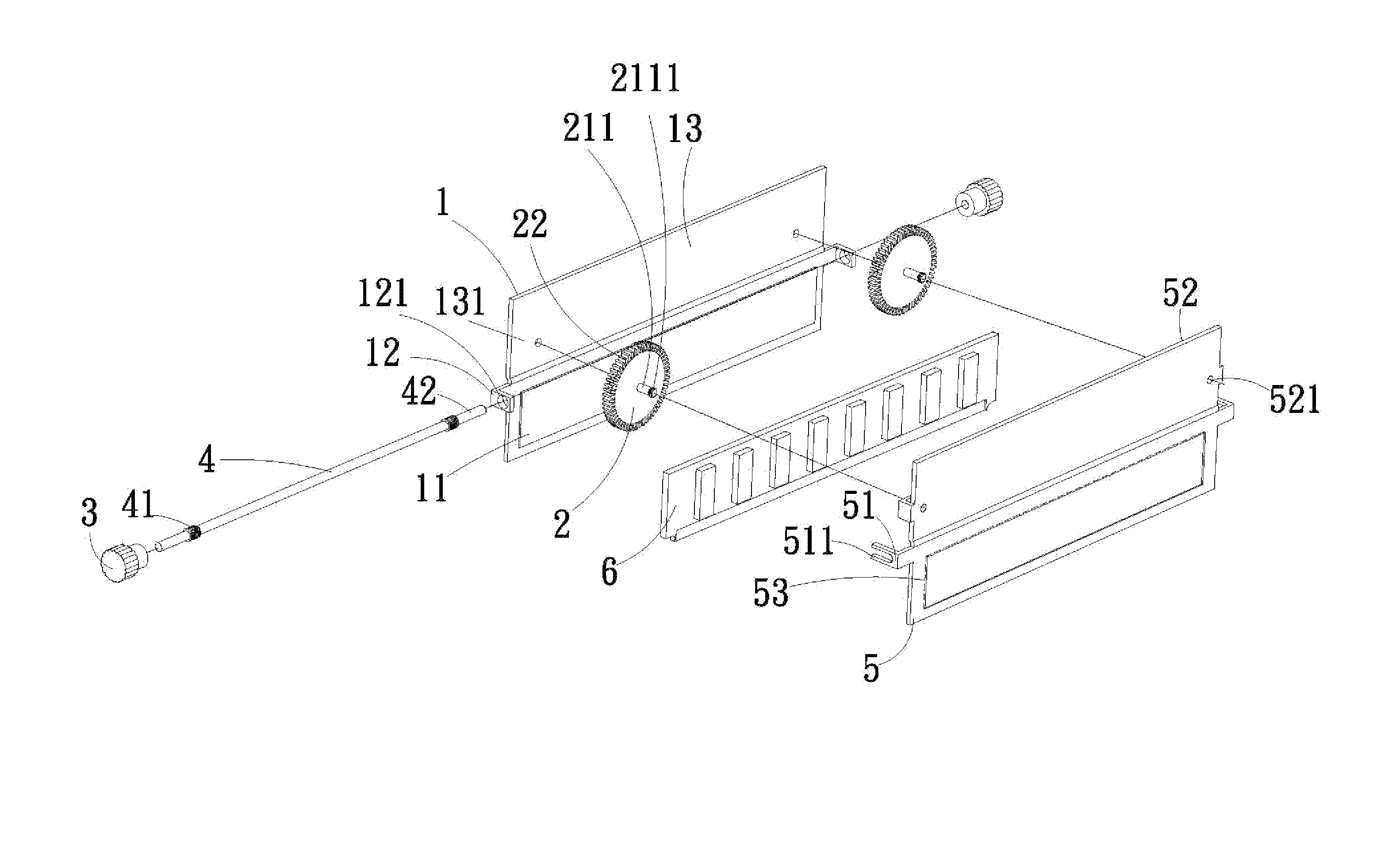
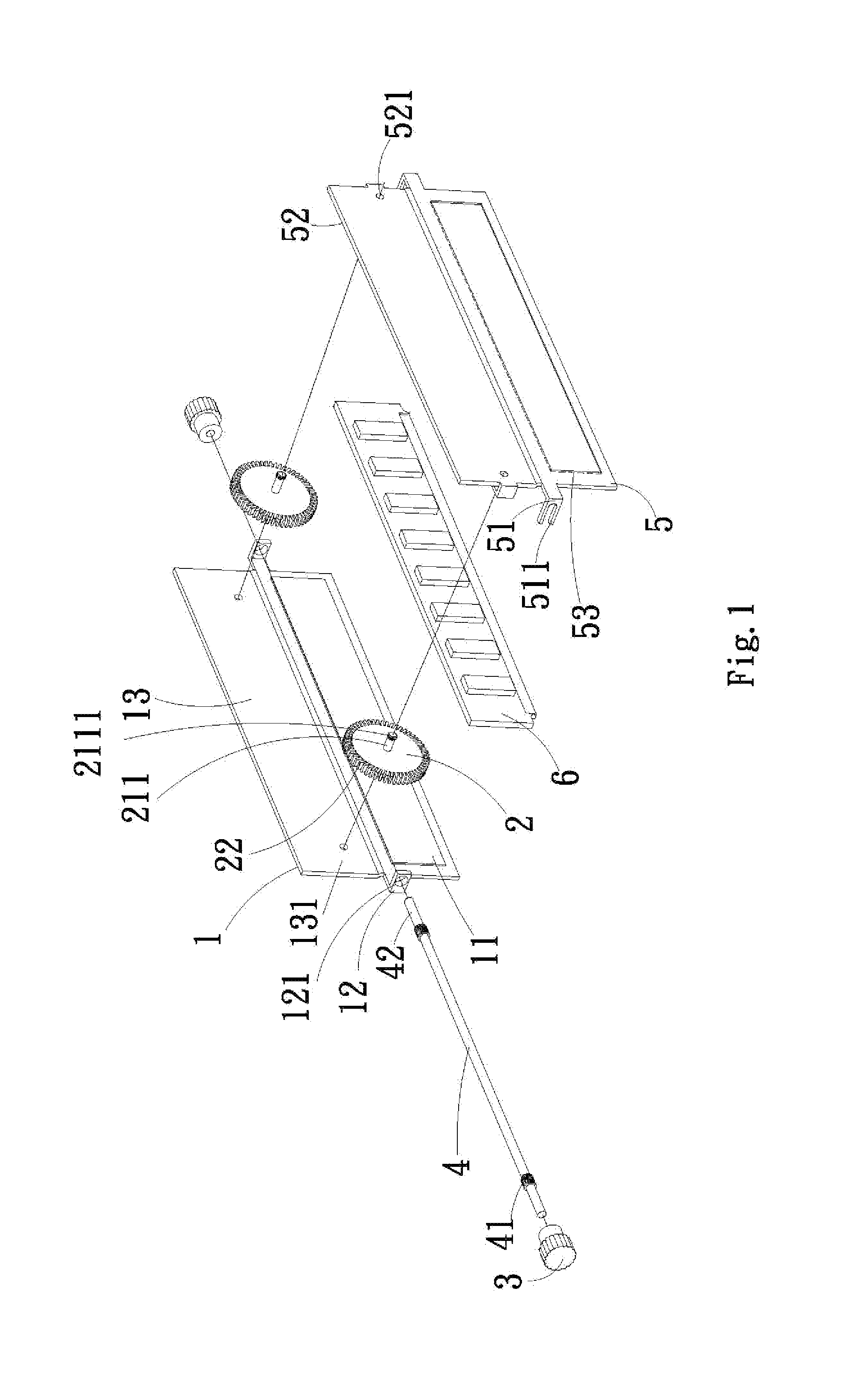
[0022]Please refer to FIG. 1 that is an exploded perspective view of a heat sink mechanism according to a preferred embodiment of the present invention. As can be clearly seen from FIG. 1, the heat sink mechanism according to the present invention includes a fixed clamping piece 1, at least one adjusting gearwheel 2, an adjusting worm shaft 4, and a movable clamping piece 5.

[0023]The fixed clamping piece 1 is provided at two longitudinally opposite ends with a shaft holder 12 each. Each of the shaft holders 12 has a through shaft hole 121 formed thereon. The fixed clamping piece 1 has an inner upper surface 13 that is provided at a predetermined position with at least one shaft hole 131, and an inner lower contact surface 11 for bearing against a heat-producing source 6.

[0024]The movable clamping piece 5 is arranged in parallel with the fixed clamping piece 1 and provided at two longitudinally opposite ends with a shaft holder 51 each. Each of the shaft holders 51 has a slot 511 for...


PUM


Abstract

A heat sink mechanism includes a fixed and a movable clamping piece, at least one adjusting gearwheel rotatably mounted to and between the fixed and the movable clamping piece via a fixing shaft while an end of the fixing shaft is screwed to the movable clamping piece, and an adjusting worm shaft rotatably mounted to the fixed clamping piece for driving the adjusting gearwheel to rotate via meshed worm threads on the worm shaft and gear teeth on the adjusting gearwheel. When the adjusting worm shaft is rotated, the meshed worm threads and gear teeth bring the adjusting gearwheel and the fixing shaft thereof to rotate, so that the movable clamping piece screwed to the rotating fixing shaft is brought to move toward or away from the fixed clamping piece to thereby fix the heat sink mechanism to a heat-producing source to achieve the purpose of heat dissipation.

Description

FIELD OF THE INVENTION[0001]The present invention relates to a heat sink assembly for a beat memory, and more particularly to a heat sink mechanism for rise outside a memory to dissipate heat produced by the memory during the operation thereof, so as to protect internal chips against damage due to high temperature.BACKGROUND OF THE INVENTION[0002]Electronic apparatus with extremely high operating performance have been constantly developed by the high-tech industrial field. With the enhanced operating performance and speed, heat-producing elements inside the electronic apparatus produce more heat during the operation thereof. Therefore, it has become an important issue to develop modular heat sink for mounting to different heat-producing sources for lowering the temperature thereof. Similarly, with the increased speed in accessing data, a memory in the electronic apparatus consumes more electric current than before and accordingly, produces more heat during the operation thereof. Whe...

Claims


Application Information

Patent Timeline
Patent Type & Authority Applications(United States)
IPC IPC(8): F16H1/16G05G1/00
CPCH01L23/40H01L23/467H01L2023/4075Y10T74/19828Y10T74/2133H01L2924/0002Y10T74/19688H01L2924/00
Inventor CHIANG, SHIH-CHIEHLEE, LIN-YU
Owner ASIA VITAL COMPONENTS SHENZHEN CO LTD
Why Eureka
Try Eureka