Designer-style dimmer apparatus and method

a dimmer switch and design-style technology, applied in contact mechanisms, process and machine control, instruments, etc., can solve the problems of dimmers that are traditionally expensive, comparatively expensive, exorbitantly expensive, etc., and the dimmers at the lower end of the cost spectrum are typically still much more expensive than simple switches

Inactive Publication Date: 2009-06-25
LEVITON MFG
View PDF17 Cites 9 Cited by
  • Summary
  • Abstract
  • Description
  • Claims
  • Application Information

AI Technical Summary

Benefits of technology

[0019]The range of motion may include a middle, effectively equidistant from the extremes of motion. Likewise, the first and second micro switches may collectively bias the rocker toward the middle.
[0020]In certain embodiments, a system in accordance with the invention may control distribution of current to a light by using a master switch and a slave switch. Each may include a rocker connected to a single frame to pivot with respect thereto. The motion may be linear, rotary, or pivotal through a range between first second extremes, opposite one another

Problems solved by technology

Such “dimmers” have traditionally been in one of two categories, comparatively expensive, and exorbitantly expensive.
Dimmers at the lower end of the cost spectrum are typically still much more expensive than simple switches, often by an order of magnitude or more.
The lower end dimmers, moreover, are usually comparatively complex, involving many small and interrelated parts, both electrical and mechanical.
Accordingly, durability is often poor as the weakest link fails.
Each dimmer is usually isolated to its own one location, due to cost or functionality.
Thus, multiple switchplates in a room often cannot host dimmers equally effective to dim lights in a room.
Many dimmers are inconvenient, and may include multiple actuators that must be used for functions such as on-off versus dimming.
Many are not easily adjusted.
This uniqueness renders them uniquely unfashionable or even unsightly.
However, these systems can represent a significant fraction of the cost of a building or residence.

Method used


Image

  • Designer-style dimmer apparatus and method
  • Designer-style dimmer apparatus and method
  • Designer-style dimmer apparatus and method

Examples


Embodiment Construction

[0049]It will be readily understood that the components of the present invention, as generally described and illustrated in the drawings herein, could be arranged and designed in a wide variety of different configurations. Thus, the following more detailed description of the embodiments of the system and method of the present invention, as represented in the drawings, is not intended to limit the scope of the invention, as claimed, but is merely representative of various embodiments consistent with the invention. The illustrated embodiments of the invention will be best understood by reference to the drawings, wherein like parts are designated by like numerals throughout.

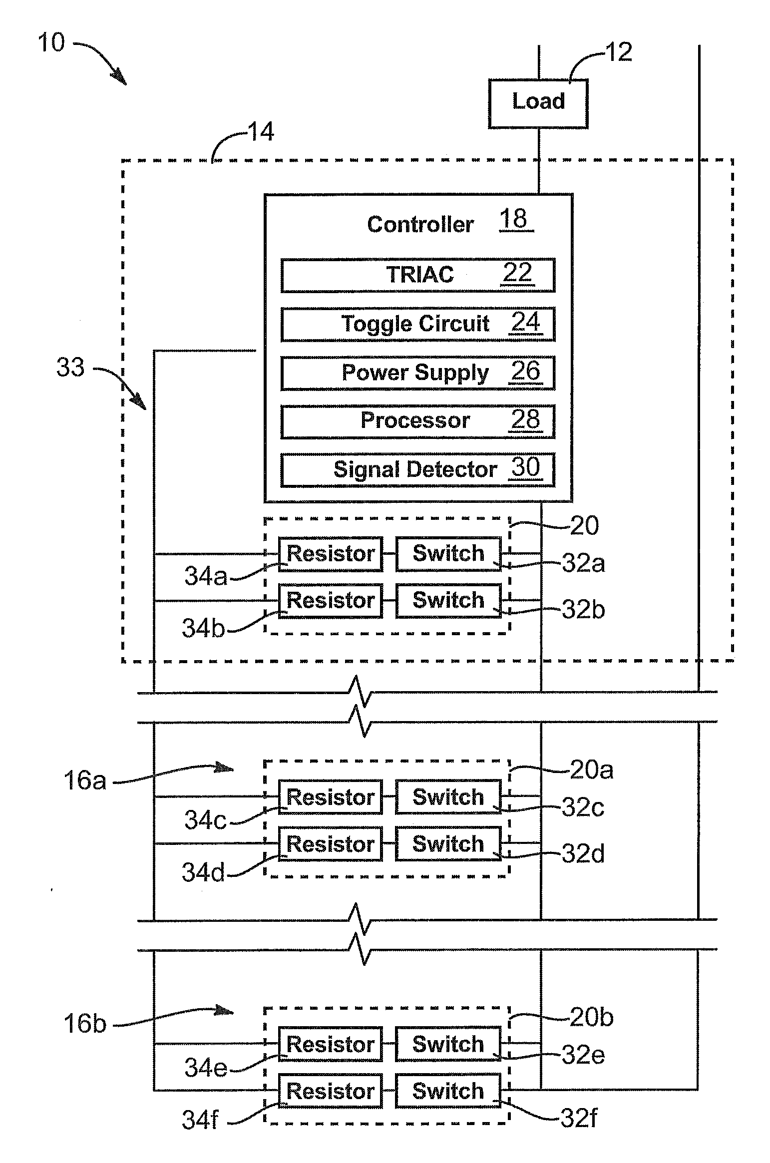
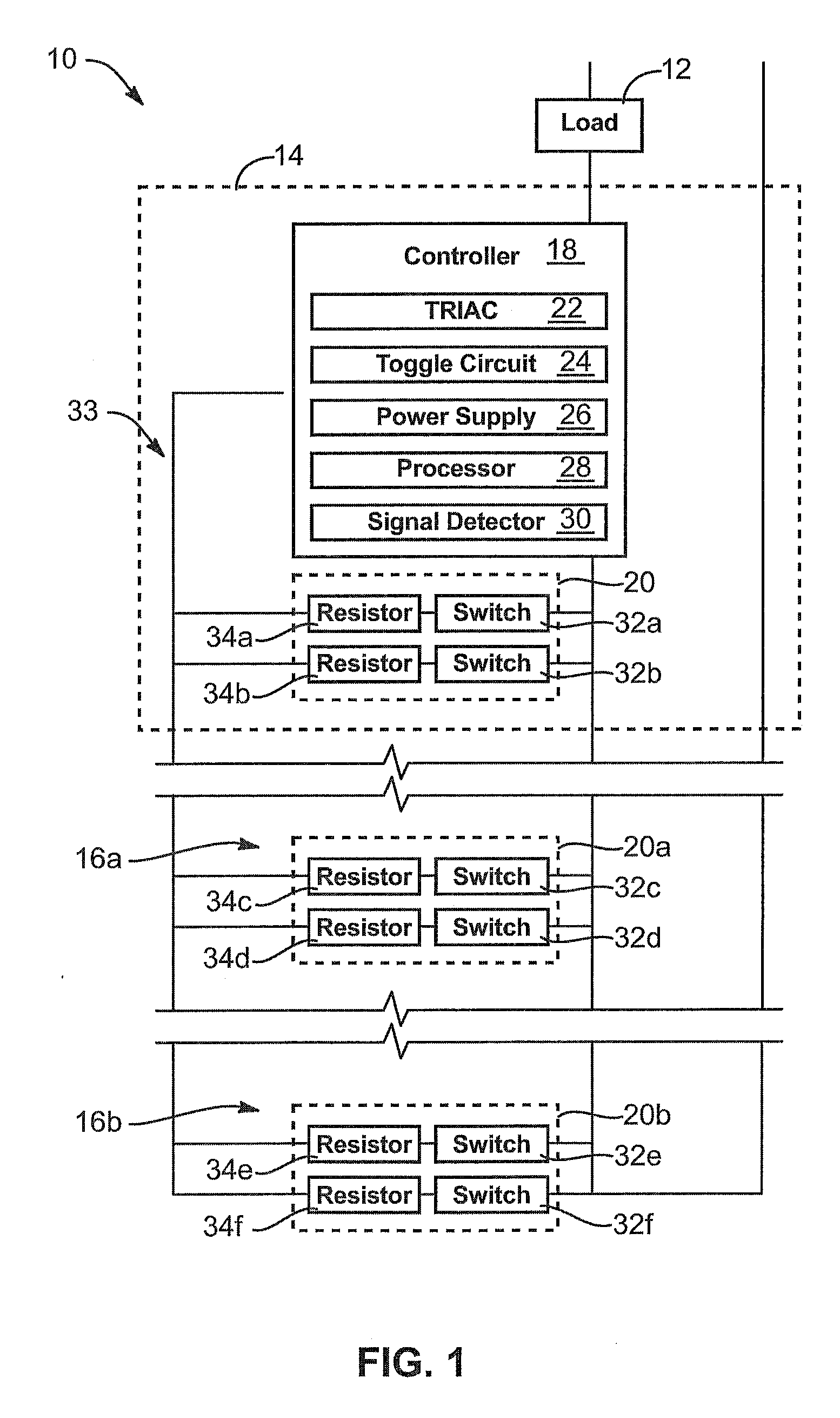
[0050]Referring to FIG. 1, a system 10 in accordance with the present invention may provide a “dimmer” for a load 12 (e.g., one or more lights 12). While “dimming” taken literally may mean decreasing the intensity of light, a dimmer is a term of art applied to devices capable of increasing and decreasing the intensi...


PUM


Abstract

A switch for controlling distribution of power to a light. The switch may include a frame, a controller connected to the frame, and a rocker connected to the frame to pivot with respect thereto through a range of motion having a first extreme and a second extreme, opposite the first extreme. The switch may also include a signal generator connected to the frame and comprising a first micro switch positioned to be actuated by the rocker pivoting toward the first extreme and a second micro switch positioned to be actuated by the rocker pivoting toward the second extreme. The controller may be connected to the signal generator to receive input therefrom and comprise logic to control the distribution in accordance with the input.

Description

RELATED APPLICATIONS[0001]This application claims the benefit of co-pending U.S. Provisional Patent Application Ser. No. 61 / 015,667 filed Dec. 21, 2007.BACKGROUND[0002]1. The Field of the Invention[0003]This invention relates to electrical switches and, more particularly, to novel systems and methods for dimmer switches.[0004]2. The Background Art[0005]Incandescent lights operate by heating a filament with electrical current until the filament glows, typically white or nearly so in many applications. Typically, lights have a rating of power consumption (e.g., wattage) and light output (e.g., lumens, candlepower, etc.). Controlling the level of light emitted by a particular unite (e.g., light bulb) may be done by controlling the current passed through the filament.[0006]To control ambiance, mood, or the like, a user may rely on a dimmer to set the power or current delivery to a light, thus setting the amount of light output by a light or array of lights. As controllers have developed...

Claims


Application Information

Patent Timeline
Patent Type & Authority Applications(United States)
IPC IPC(8): H05B37/02H01H3/00
CPCH05B37/0263H01H23/30H05B47/185
Inventor BURRELL, DOUGLASCLARE, DAVID
Owner LEVITON MFG
Why Eureka
Try Eureka