
Folding treadmill

a treadmill and folding technology, applied in the field of treadmills, can solve the problems of weak handle structures disclosed in the aforesaid patents, user loss of balance and fall backward, and unstable handrails

Inactive Publication Date: 2009-06-25
JOHNSON HEALTH TECH
View PDF25 Cites 37 Cited by
  • Summary
  • Abstract
  • Description
  • Claims
  • Application Information

AI Technical Summary

Benefits of technology

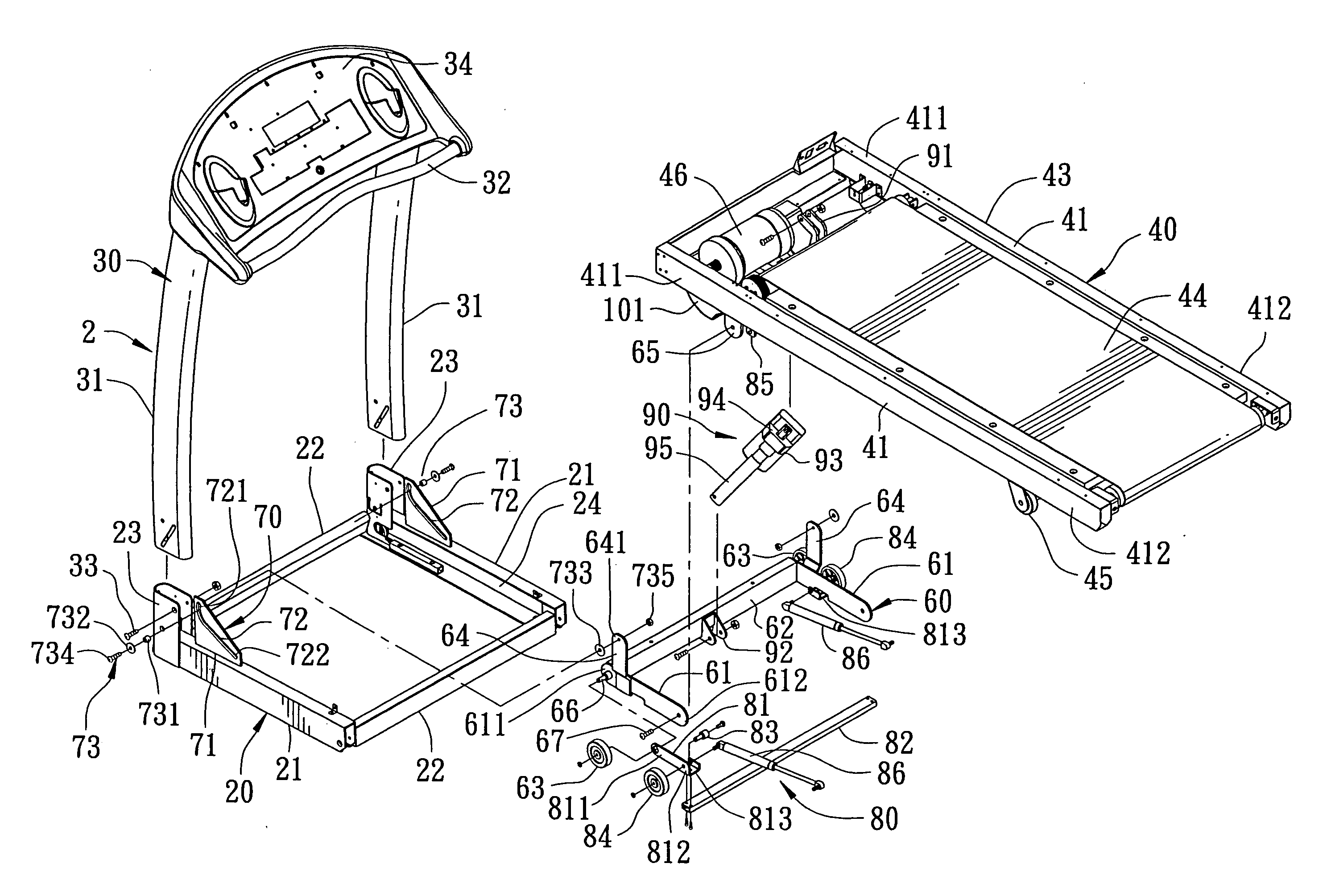
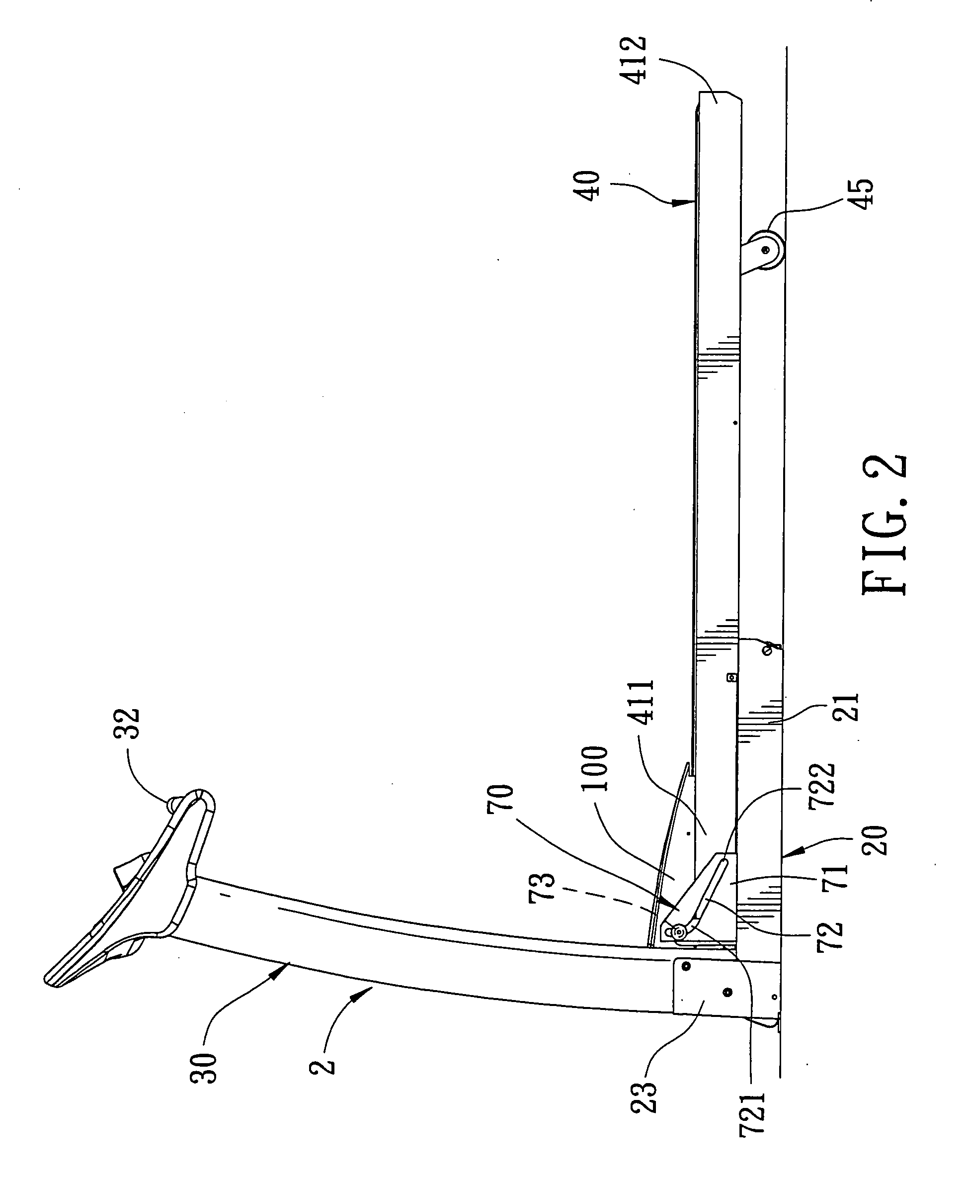
The present invention provides a folding treadmill with a tread base that can be moved rearward when folded upward, so as to not interfere with the console or control board mounted on an upright structure. The tread base can be folded to a nearly vertical position without interfering with the console or control board. The folding treadmill also has a stable construction that can stabilize the tread base, especially when the tread base is in a folded position. The folding treadmill includes a base support, guider, pivot member, tread base, and first roller. The tread base can turn between a folded position and an unfolded position and move rearward or forward when turned to the folded or unfolded position, respectively. The folding treadmill provides a convenient and compact exercise device that can be easily moved and stored when not in use.

Problems solved by technology

However, the collapsible design of the handrails renders the handrails unstable.
Thus, when a user grips the handrails for support while walking or jogging on the treadmill, the user may lose balance and fall backward.
However, the handle structures disclosed in the aforesaid patents are weak.
However, since the rollers move only in a vertical direction, the movement of the tread base is restricted by the vertical slide rails so that the tread base moves only upward or downward while the tread base is folded or elevated to its inclined position.
However, the construction of the console is complicated since the console must be pivotal about the hinge in order to avoid interference.

Method used


Image

  • Folding treadmill
  • Folding treadmill
  • Folding treadmill

Examples


Embodiment Construction

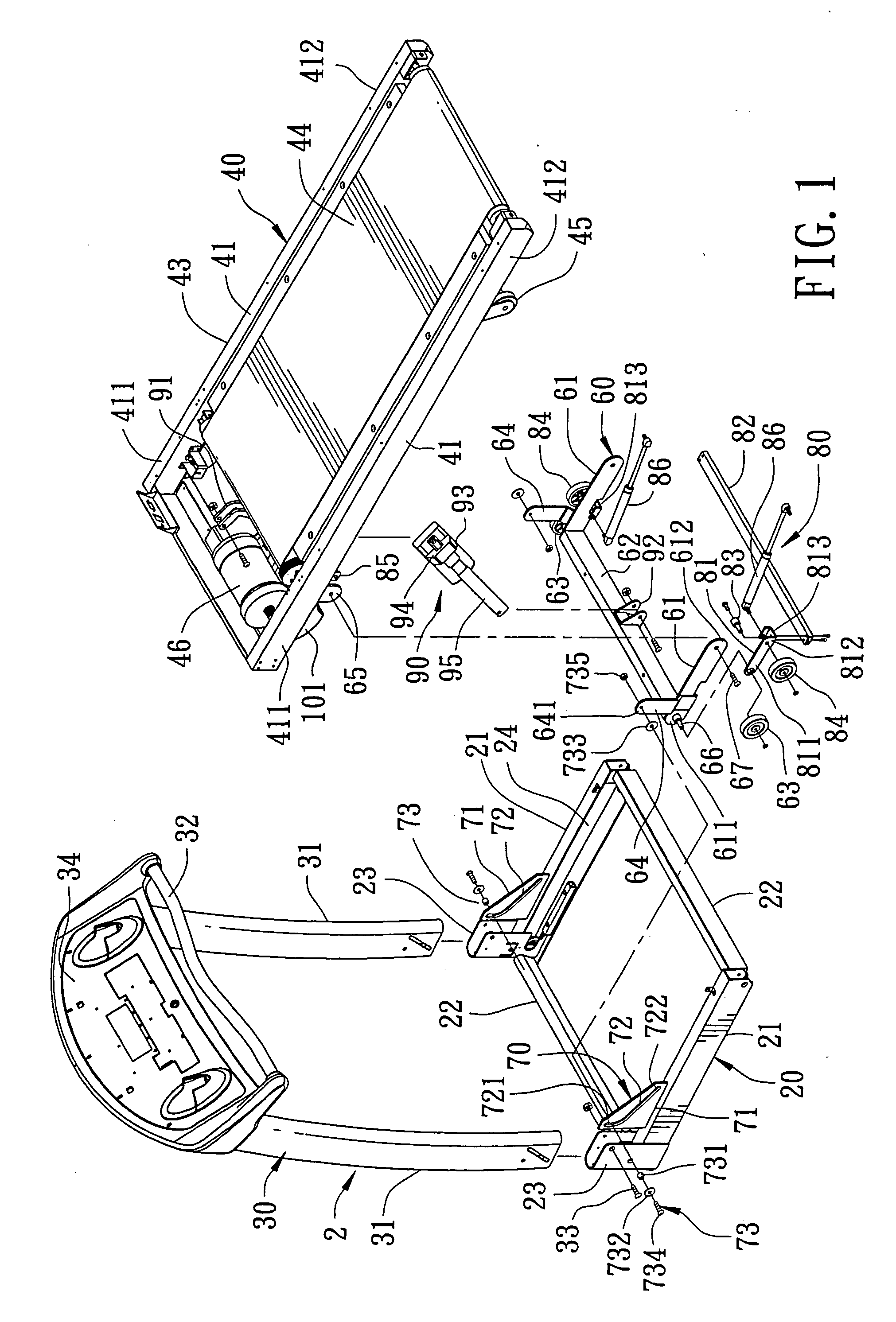
[0025]Referring to FIGS. 1, 2, and 2A, a preferred embodiment of a folding treadmill according to the present invention is shown to comprise a base support 2, and a tread base 40 mounted on the base support 2. The base support 2 includes a foot structure 20 and an upright structure 30 extending upward from the foot structure 20. The foot structure 20 has left and right bars 21 which are interconnected by front and rear bars 22 provided at front and rear ends of the foot structure 20. A guide rail structure includes left and right guide rails or grooves 24 which are provided respectively in inner sides of the left and right bars 21.

[0026]The upright structure 30 includes two upright tubes 31 and a top panel 34 mounted to top ends of the upright tubes 31. A handle 32 is associated with the top panel 34. The upright tubes 31 are respectively fixed to two positioning posts 23 which extend upward respectively from front ends of the side bars 21.

[0027]The tread base 40 includes a frame 43...


PUM


Abstract

A folding treadmill includes a tread base supported by a foot structure which has guide plates formed with elongated slots on two sides of the tread base. The tread base is connected pivotally on the base support through pivot members which are mounted movably within the respective slots so that the tread base is turnable between a folded position and an unfolded position and movable rearward when the tread base turns to the folded position or forward when the tread base turns to the unfolded position. The foot structure further includes a guide rail structure on two sides of the tread base to support movably a first roller which is attached to the tread base and a lifting device for lifting the tread base.

Description

CROSS-REFERENCE TO RELATED APPLICATION[0001]This is a continuation of U.S. patent application Ser. No. 10 / 884,443, entitled “Folding Treadmill,” filed Jan. 5, 2006.BACKGROUND[0002]1. Field of the Invention[0003]This invention relates to a treadmill, more particularly to a folding treadmill having a tread base movable rearward or forward relative to a base support when turning to a folded or unfolded position.[0004]2. Description of the Related Art[0005]Treadmills are popular exercise apparatuses which permit a user to perform physical activities, such as walking, jogging or running movements, so as to exercise the cardiovascular system and the other parts of the body. Since treadmills are bulky and occupy a considerable space, it becomes a trend to design a treadmill with a foldable tread base in order to decrease the volume of the treadmill when the treadmill is stored.[0006]U.S. Pat. No. 5,899,834 discloses a foldable treadmill with a deck having a rear end that is hingedly attach...

Claims


Application Information

Patent Timeline
Patent Type & Authority Applications(United States)
IPC IPC(8): A63B22/02
CPCA63B22/0023A63B2210/50A63B22/0235A63B22/02
Inventor HUANG, TE-CHANGHSU, CHUNG-TSENGCHIU, WEN-PIN
Owner JOHNSON HEALTH TECH
Learn More