Method for producing print

a printing method and print technology, applied in printing, lamination, chemistry apparatus and processes, etc., can solve the problems of degrading the quality of the resulting print, and achieve the effect of clear differences in surface glossiness and visual asperities

Active Publication Date: 2009-07-02
SONY CORP
View PDF9 Cites 6 Cited by
  • Summary
  • Abstract
  • Description
  • Claims
  • Application Information

AI Technical Summary

Benefits of technology

[0034]According to the above-described method, because the difference (a−b) between the glossiness a and the glossiness b is 60 or more, visual asperities can be easily imparted to the resulting print. In other words, the pattern for creating the difference in surface glossiness can be clearly formed during transfer of the image-protecting layer. Thus, clear differences in surface glossiness can be achieved.

Problems solved by technology

Although a print having a halide photo-like texture can be obtained by using paper in the supporting base member, a desired pattern with clear differences in glossiness is rarely formed and quality of the resulting print is degraded since the intermediate layer containing hollow particles thermally swell in a region onto which high energy is applied during lamination of the image-protecting layer.

Method used


Image

  • Method for producing print
  • Method for producing print
  • Method for producing print

Examples


Embodiment Construction

[0041]An embodiment of a method for making a print will now be described with reference to drawings.

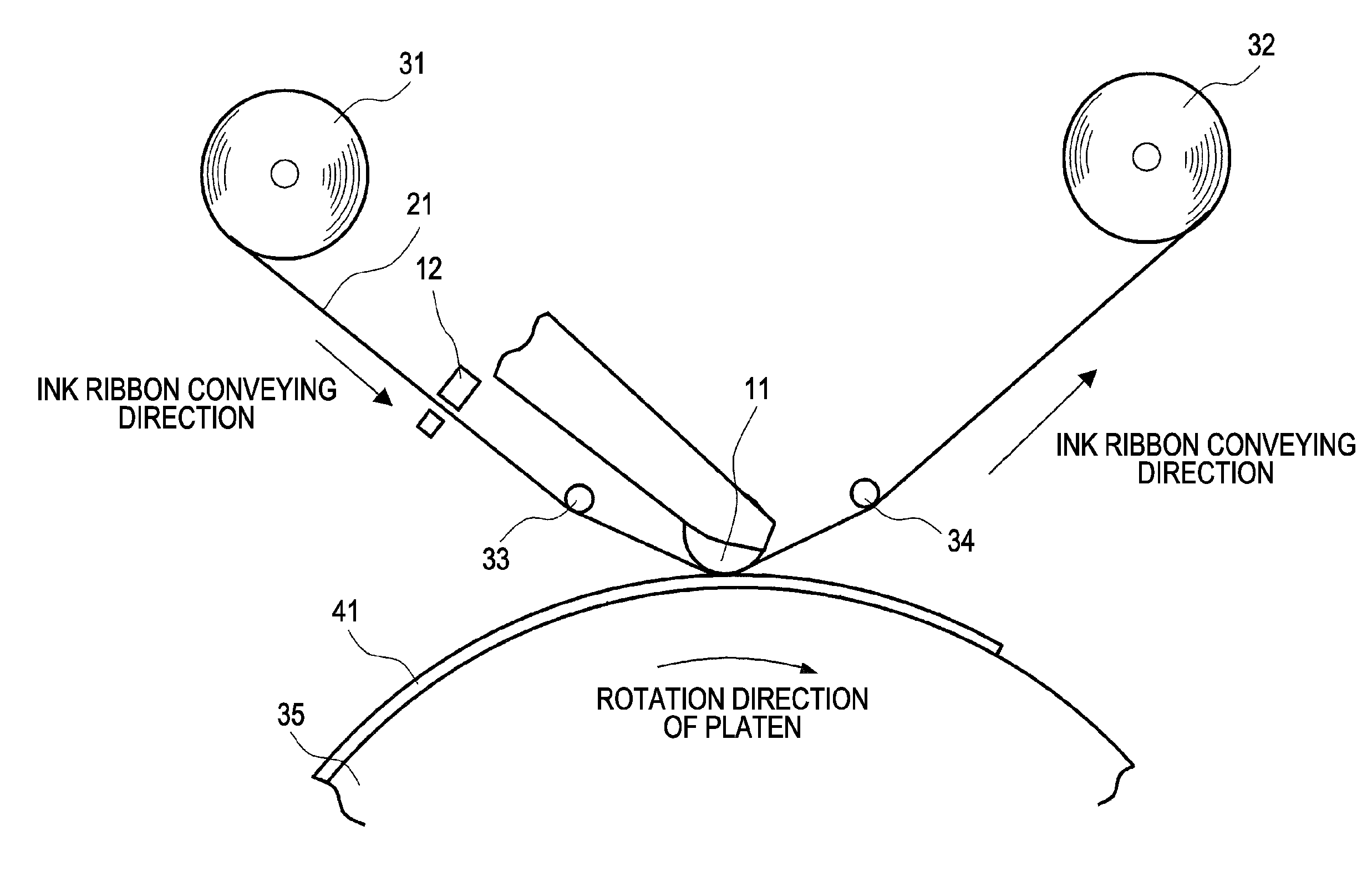
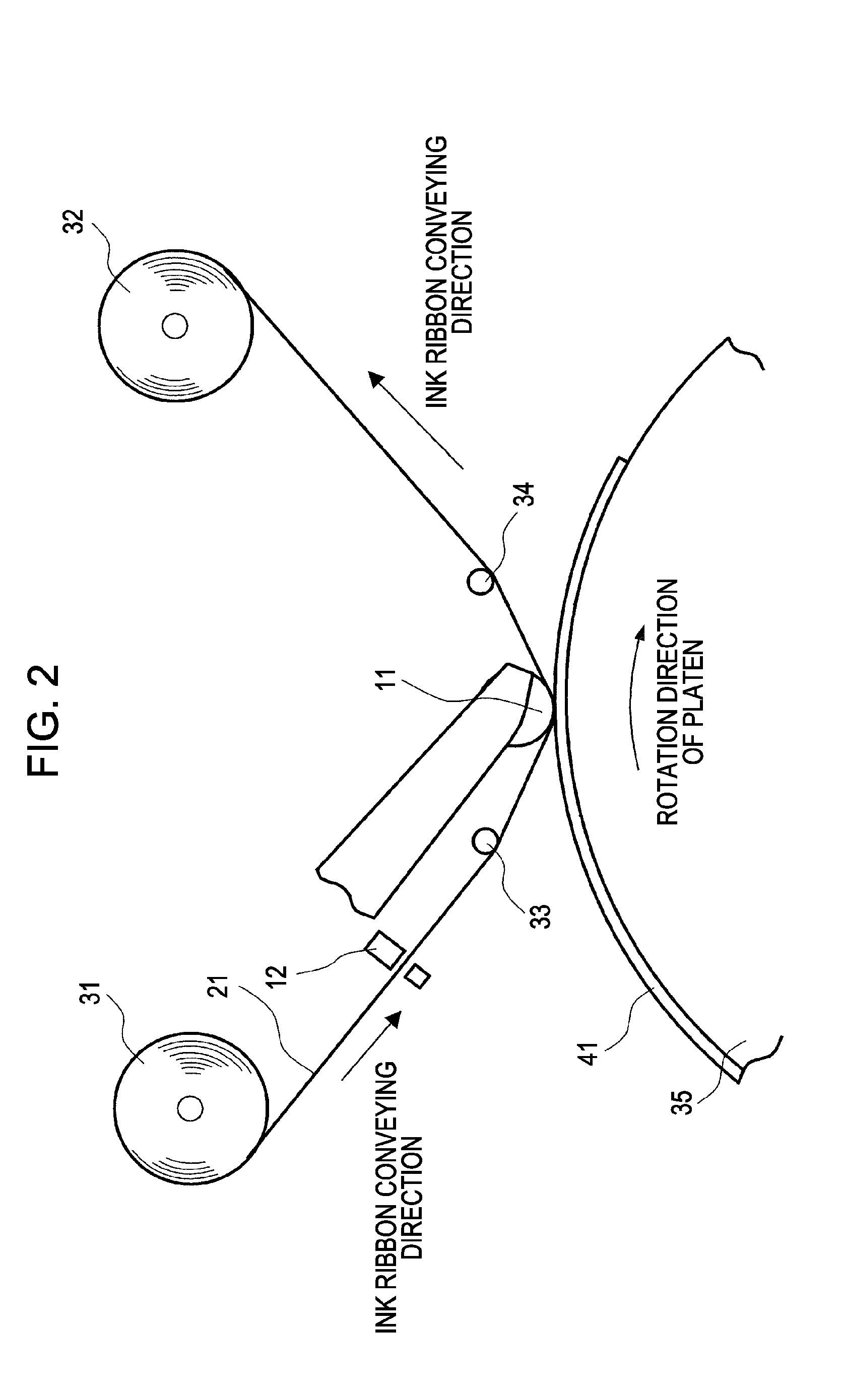
[0042]First, a main printing unit of a printing apparatus used for implementing the method of the embodiment is described by referring to a schematic diagram in FIG. 2.

[0043]As shown in FIG. 2, the main printing unit includes a supply reel 31 for supplying a thermal transfer sheet (hereinafter also referred to as “ink ribbon”) 21 and a winding reel 32 that winds the ink ribbon 21. The main printing unit also includes guide rollers 33 and 34 for guiding the ink ribbon 21 to a printing position. A thermal transfer head 11 that forms a printing position is disposed between the guide rollers 33 and 34.

[0044]The main printing unit also includes a platen 35 that rotates and conveys an image-receiving sheet (hereinafter also referred to as “printing paper”) 41 to the printing position corresponding to the thermal transfer head 11.

[0045]Examples of details of the main printing unit having the...


PUM

PropertyMeasurementUnit
particle diameteraaaaaaaaaa

Abstract

A method for producing a print includes a step of thermally bonding a thermally transferrable image-protecting layer onto an image surface of an image-receiving sheet so as to form a protective layer. In this step, thermal energy applied is changed so that the resulting protective layer has a first glossy region and a second glossy region having a glossiness lower than that of the first glossy region. The first glossy region has a glossiness a, which is a 20° mirror-surface glossiness measured according to Japanese Industrial Standard Z8741. The second glossy region has a glossiness b, which is a 20° mirror-surface glossiness measured according to Japanese Industrial Standard Z8741. The value obtained by subtracting the glossiness b from the glossiness a is 60 or more.

Description

CROSS REFERENCES TO RELATED APPLICATIONS[0001]The present invention contains subject matter related to Japanese Patent Application JP 2007-335878 filed in the Japanese Patent Office on Dec. 27, 2007, the entire contents of which are incorporated herein by reference.BACKGROUND OF THE INVENTION[0002]1. Field of the Invention[0003]The present invention relates to a method for producing a print.[0004]2. Description of the Related Art[0005]Images formed on objects such as printing paper, in particular, images formed by a sublimation thermal transfer process using a sublimation dye or a thermally diffusible dye, have been laminated with transparent films to protect the surfaces of the images.[0006]The image protecting functions desired for the transparent films vary widely and include following: to block gas that causes image deterioration, to prevent changes in color of the images by imparting a ultraviolet (UV) absorbing function to the transparent films, to impart plasticizer resistanc...

Claims


Application Information

Patent Timeline
Patent Type & Authority Applications(United States)
IPC IPC(8): B32B37/00
CPCB41M7/0027
Inventor KOIKE, YOSHIFUMI
Owner SONY CORP
Why Eureka
Try Eureka