Multi-probe time sequence calibration jig and calibration method

A timing calibration and multi-probe technology, applied in the field of probe detection

Inactive Publication Date: 2021-04-20
GUANGDONG VTRON TECH CO LTD
View PDF7 Cites 0 Cited by
  • Summary
  • Abstract
  • Description
  • Claims
  • Application Information

AI Technical Summary

Problems solved by technology

[0005] The present invention aims to overcome at least one defect of the above-mentioned prior art, and provides a multi-probe timing calibration fixture, which is used to solve the problem of how to use an oscilloscope to simultaneously perform timing calibration on multiple probes and eliminate timing differences between multiple probes , and further provide a calibration method, using a multi-probe timing calibration fixture to quickly and accurately perform timing calibration on multiple probes

Method used


Image

  • Multi-probe time sequence calibration jig and calibration method
  • Multi-probe time sequence calibration jig and calibration method

Examples


Embodiment 1

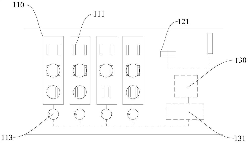
[0027] like figure 1 As shown, this embodiment is a multi-probe timing calibration fixture 100, including: two detection channels 110; each detection channel 110 is provided with three detection bits 111 for connecting with the probes, and each detection channel 110 is connected to one The detection bit 111; the clock generator 131 is electrically connected with the detection channel 110, and provides a unified clock signal for the detection channel 110; the controller 130 is electrically connected with the clock generator 131, and controls the operation of the clock generator 131; the controller 130 is used for It is connected to the oscilloscope 200 , and the trigger timing of the probe detection is adjusted by adjusting the Deskew parameter of the probe connected to the oscilloscope 200 .

[0028] The multi-probe timing calibration jig 100 is used in conjunction with the oscilloscope 200 to be applicable to the oscilloscopes 200 with different numbers of ports 240 , and ena...

Embodiment 2

[0037] This embodiment is a multi-probe timing calibration fixture 100, including: four detection channels 110; each detection channel 110 is provided with two detection bits 111 for connecting with probes, and each detection channel 110 is connected to a detection bit 111; the clock generator 131 is electrically connected with the detection channel 110, and provides a unified clock signal for the detection channel 110; the controller 130 is electrically connected with the clock generator 131, and controls the operation of the clock generator 131; the controller 130 is used to communicate with the oscilloscope 200, and adjust the trigger timing of the probe detection by adjusting the Deskew parameters of the probe connected to the oscilloscope 200.

[0038] The multi-probe timing calibration jig 100 is used in conjunction with the oscilloscope 200 to be applicable to the oscilloscopes 200 with different numbers of ports 240 , and enables all connected probes on the oscilloscope...

Embodiment 3

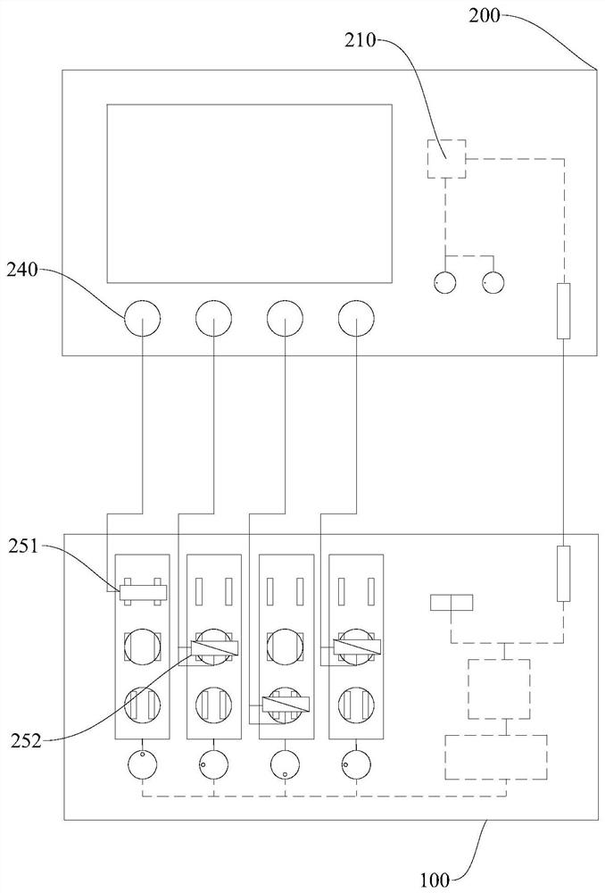
[0045]This embodiment is a probe timing calibration method using the multi-probe timing calibration jig 100. Two single-ended probes 251 and two differential probes 252 to be used are respectively installed on the test ports 240, CH1 and CH2 of the oscilloscope 200. , CH3 and CH4, the test ends of the four probes are connected to the corresponding detection bits 111 on the four channels from left to right on the multi-probe timing calibration fixture 100; the controller 130 is connected to the control chip 210 of the oscilloscope 200 Connect the oscilloscope 200 and the multi-probe timing calibration jig 100 to power. The specific method: start the multi-probe timing calibration fixture 100 and the oscilloscope 200, jog the automatic calibration button 121 of the multi-probe timing calibration fixture 100, and the controller 130 of the multi-probe timing calibration fixture 100 controls the clock generator 131 to four The corresponding detection bit 111 on each detection chann...


PUM


Abstract

The invention relates to the field of probe detection, in particular to a multi-probe time sequence calibration jig, which comprises: at least two detection channels; wherein each detection channel is provided with at least two detection positions used for being connected with a probe, and each detection channel is connected to one detection position each time; a clock generator, which is electrically connected with the detection channels and provides a unified clock signal for the detection channels; a controller, which is electrically connected with the clock generator and controls the clock generator to operate; the controller is used for being connected with an oscilloscope, and the triggering time sequence of probe detection is adjusted by adjusting Deskew parameters of a probe connected with the oscilloscope. The technical effect that the oscilloscope can quickly and precisely perform time sequence calibration on multiple probes is realized from the three aspects of supplementing necessary conditions of time sequence calibration, perfecting a test environment of time sequence calibration and optimizing an operation process of time sequence calibration.

Description

technical field [0001] The invention relates to the field of probe detection, and more specifically, to a multi-probe timing calibration jig and a calibration method. Background technique [0002] Signal testing is a common test in the development or testing of electronic products. Commonly used signal testing includes: single-ended testing of test circuit components to ground signals, such as parallel data bus testing; differential testing of positive voltage to negative voltage signals of test circuit components, such as DDR test. A single-ended probe is commonly used for single-ended testing, while a differential probe is commonly used for differential testing. In a test, it is often only necessary to test the signal of a single port, and more to test the combined signal of multiple components in the entire board at the same time. This test often requires the cooperation of multiple different types of probes to complete. [0003] Probe timing difference is one of the in...

Claims


Application Information

Patent Timeline
Patent Type & Authority Applications(China)
IPC IPC(8): G01R35/02G01R13/00
Inventor 方凌兰
Owner GUANGDONG VTRON TECH CO LTD
Why Eureka
Try Eureka