
Sterilizable Package With A High Barrier To Oxygen

Active Publication Date: 2009-07-02
KNPAK ACQUISITION LTD
View PDF33 Cites 14 Cited by
  • Summary
  • Abstract
  • Description
  • Claims
  • Application Information

AI Technical Summary

Benefits of technology

[0013]The three layers comprising the package may have different lengths, and the layer with the breathable and non-breathable sections may have a width less than the layers of non-breathable material. The two compartments formed by the three layers may be individually sealed via hermetic closing seals, and the closing seal of the second compartment includes only sections of the non-breathable material from the layer with the breathable and non-breathable sections. Such a seal minimizes the oxygen transmission rate for the package.

Problems solved by technology

To provide a barrier, the packaging may be formed from a foil or other high-barrier material; however, high-barrier material does not allow sterilizing gas to pass through the material into the package.
Such conventional packaging does not provide for regulation of ambient conditions such as circulation of air, exposure to oxygen or absorption of gases, moisture, etc.
Without such regulation, the efficacy of the packaging and its contents may be compromised.

Method used


Image

  • Sterilizable Package With A High Barrier To Oxygen
  • Sterilizable Package With A High Barrier To Oxygen
  • Sterilizable Package With A High Barrier To Oxygen

Examples


first embodiment

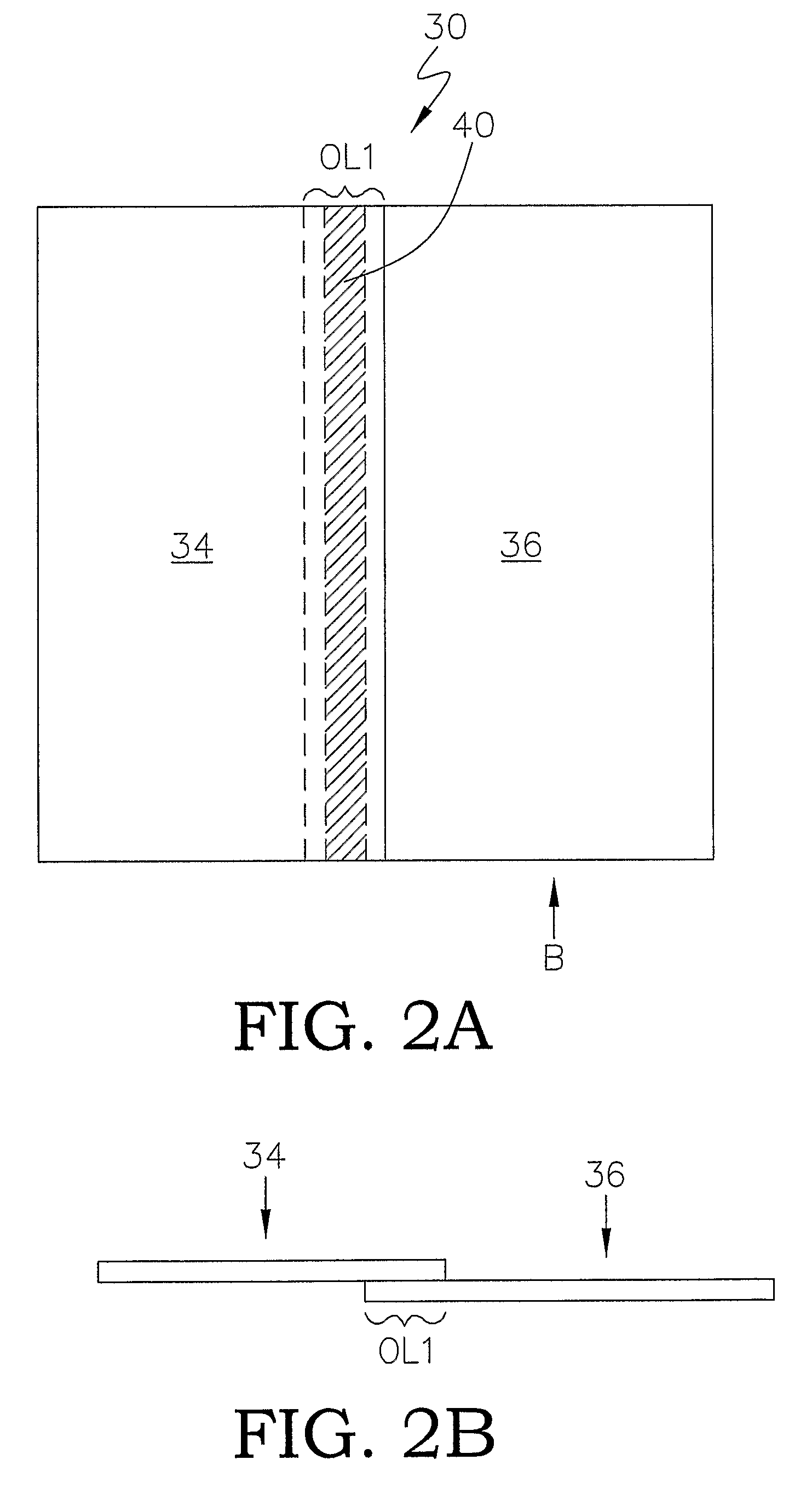
[0033]FIG. 2B is a side view of this first embodiment of the third layer 30, from the direction indicated by arrow B in FIG. 2A. This third layer 30 may have a total thickness from about 75 microns to about 225 microns. However, the thickness is not limited to these dimensions. Greater and lesser dimensions are contemplated.

[0034]FIG. 3A is a plan view of a second embodiment of the third layer. This second embodiment of the third layer 330 is similar to the first embodiment depicted in FIG. 2A and FIG. 2B but further comprises a third section 332. In this second embodiment, the first section 336, the second section 334 and the third section 332 are arranged side-by-side in a co-planar manner with the second section 334 positioned between and connecting the first section 336 and the third section 332. The second section 334 overlaps both the first section 336 and the third section 332 along opposite sides, at OL3 and OL2, respectively. The first section 336 and the second section 334...

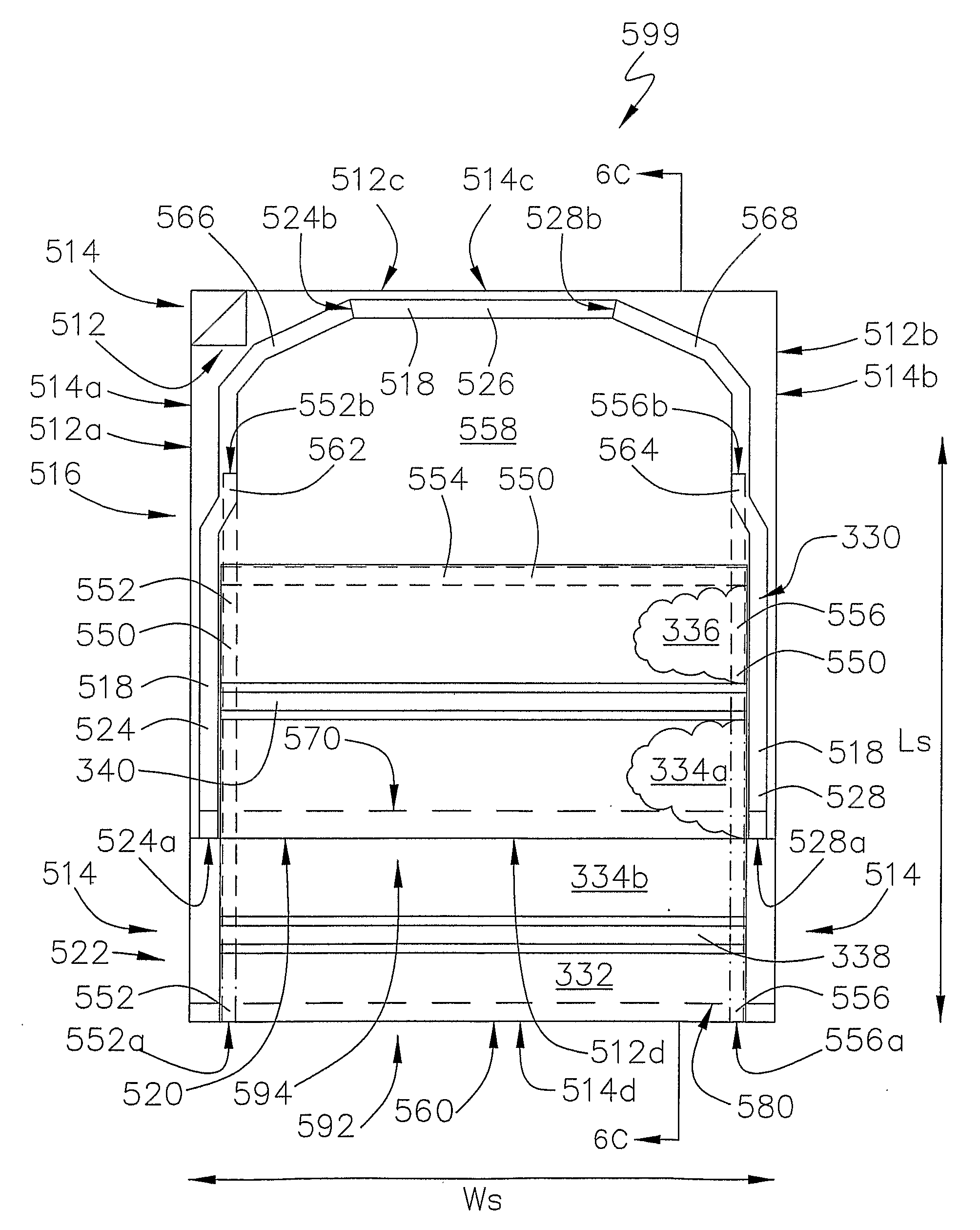
second embodiment

[0035]FIG. 3B is a side view of this second embodiment of the third layer 330, from the direction indicated by arrow C in FIG. 3A. This third layer 330 may have a total thickness from about 75 microns to about 225 microns. However, the thickness is not limited to these dimensions. Greater and lesser dimensions are contemplated.

[0036]Various materials may be used for the three layers and the sections thereof. Gurley Hill porosity values may be used to select the materials. “Gurley Hill porosity” refers to the air resistance of an approximately 6.45cm2 (1 in2) circular area of test sample using a pressure differential of 1.22 kPa and is measured in accordance with International Standard ISO 5636-5, “Paper and board—Determination of air permeance and air resistance (medium range)—Part 5: Gurley method.” Gurley Hill porosity values are reported in the amount of time (seconds) required for 100 cm3 of air to pass through the test sample. In general, Gurley Hill porosity values indicate th...


PUM


Abstract

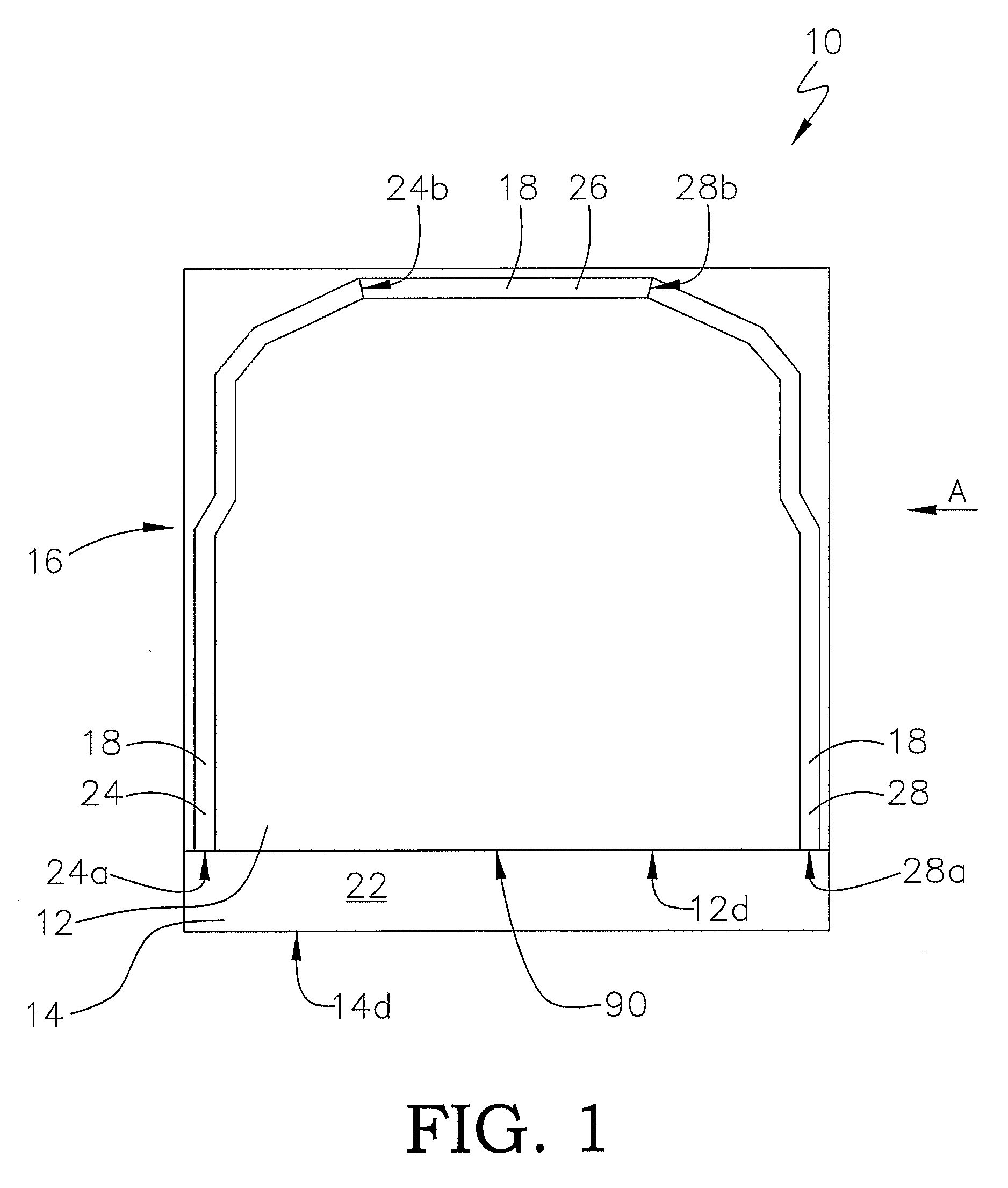
A package (599) with three layers allows sterilization of the package contents, provides a separate area for a scavenger and minimizes the oxygen transmission rate for the package and has, in one embodiment, a third layer (330) with a first section (336) of breathable polymeric material, a second section (334) of substantially non-breathable polymeric material and a third section (332) of breathable polymeric material which is positioned between a first layer (512) of substantially non-breathable polymeric material and a second layer (514) of substantially non-breathable polymeric material. The first layer (512) and the second layer (514) are fixed together to define a non-breathable pouch (516); and the third layer (330) is fixed to the first layer (512) and the second layer (514) and divides the non-breathable pouch (516) into a first compartment (592) and a second compartment (594). The outer seal (518) fixing the first layer (512) to the second layer (514) does not include any interposing first section (336) of the third layer (330).

Description

BACKGROUND OF THE INVENTION[0001]The present invention relates to packaging and, more particularly, to packaging that allows sterilization of its contents with a subsequent high barrier to the ingress of oxygen and water vapor.[0002]Many items, including, but not limited to, medical items such as drug-eluting stents, are required to be sterilized while in a package and, after sterilization, are required to be substantially isolated from oxygen and water vapor for prolonged time periods. To allow sterilization of an item in a package, the package may be formed from a breathable material that allows sterilizing gas to pass through the breathable material. These breathable materials include spun-bonded olefin products such as those sold by E.I. Du Pont de Nemours and Company (Wilmington, Del.) under the trademark TYVEK®. After sterilization and for the remainder of the life of the package, the breathable material provides a tortuous path for microbes, bacteria and other contaminants, a...

Claims


Application Information

Patent Timeline
IPC IPC(8): A61B19/02B65D30/08B65D30/22B65B55/02
CPCA61B19/026A61B2019/0268A61L2202/24A61L2/26A61L2202/181A61L2/206A61B2050/316A61B50/30
Inventor GASKELL, PAULWARD, CONOR BRENDANKING, GERRY A.
Owner KNPAK ACQUISITION LTD
Learn More