Cap drying apparatus

a drying apparatus and cap technology, applied in the field of headgear drying, can solve the problems of not having a base, not having a cage-like insert inside the cap, and not being adjustable to a range of sizes

Inactive Publication Date: 2009-07-02
BRYANT CARL E
View PDF14 Cites 5 Cited by
  • Summary
  • Abstract
  • Description
  • Claims
  • Application Information

AI Technical Summary

Benefits of technology

[0008]Another object of the present invention is to provide a drying kit for ball caps that provides both inner and outer support for keeping caps smooth during the drying process and storage.
[0009]Still another object of the present invention is to provide a simple, inexpensive, and adjustable support for ball caps that can provide uniform inside pressure such that the outer surface of the cap dries smooth and wrinkle free.
[0010]Yet another object of the present invention is to provide a cap support apparatus for maintaining the appearance of a cap during storage.

Problems solved by technology

Inflatable hat blocks have been disclosed in U.S. Pat. Nos. 716,251, 1,742,397, 2,129,720, and 2,536,913; however, these devices did not comprehend billed caps.
In addition, they do not have a base that could be used to clamp a cap bill in position thereon.
In U.S. Pat. No. 4,491,256, Payne et al disclose a drying insert for caps that has clips for engaging with the bill of a cap, but the cage-like insert fits inside the cap and is not adjustable to a range of sizes.
Grommes in U.S. Pat. No. 4,708,271 discloses a drying form for wet caps that clamps the bill to a base, but there is no inflatable device and nothing to create or maintain curvature in the bill.

Method used


Image

  • Cap drying apparatus
  • Cap drying apparatus
  • Cap drying apparatus

Examples


Embodiment Construction

, particularly, when such description is taken in conjunction with the attached drawing figures and with the appended claims.

BRIEF DESCRIPTION OF THE DRAWINGS

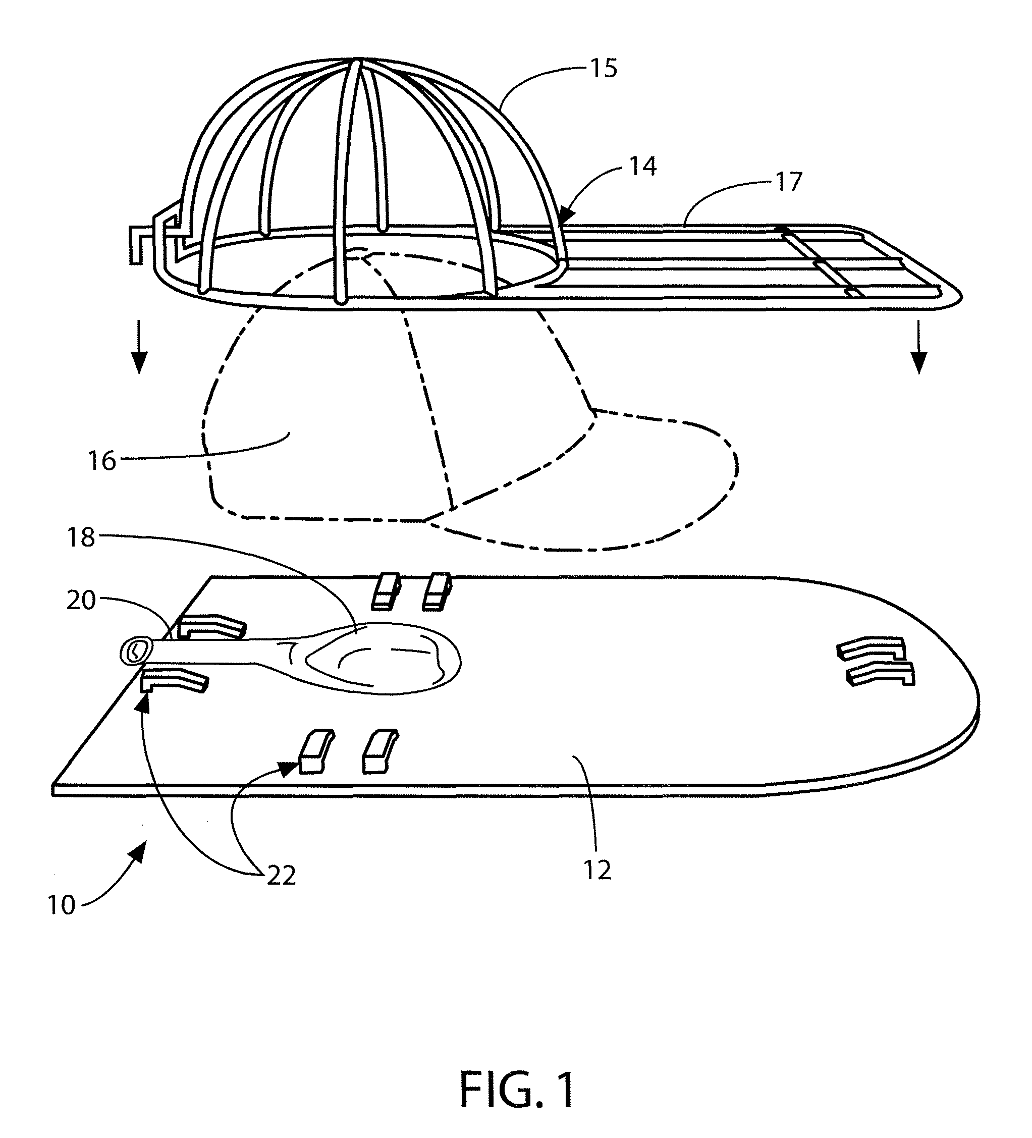
[0013]FIG. 1 is an exploded perspective view of the present invention in combination with a ball cap.

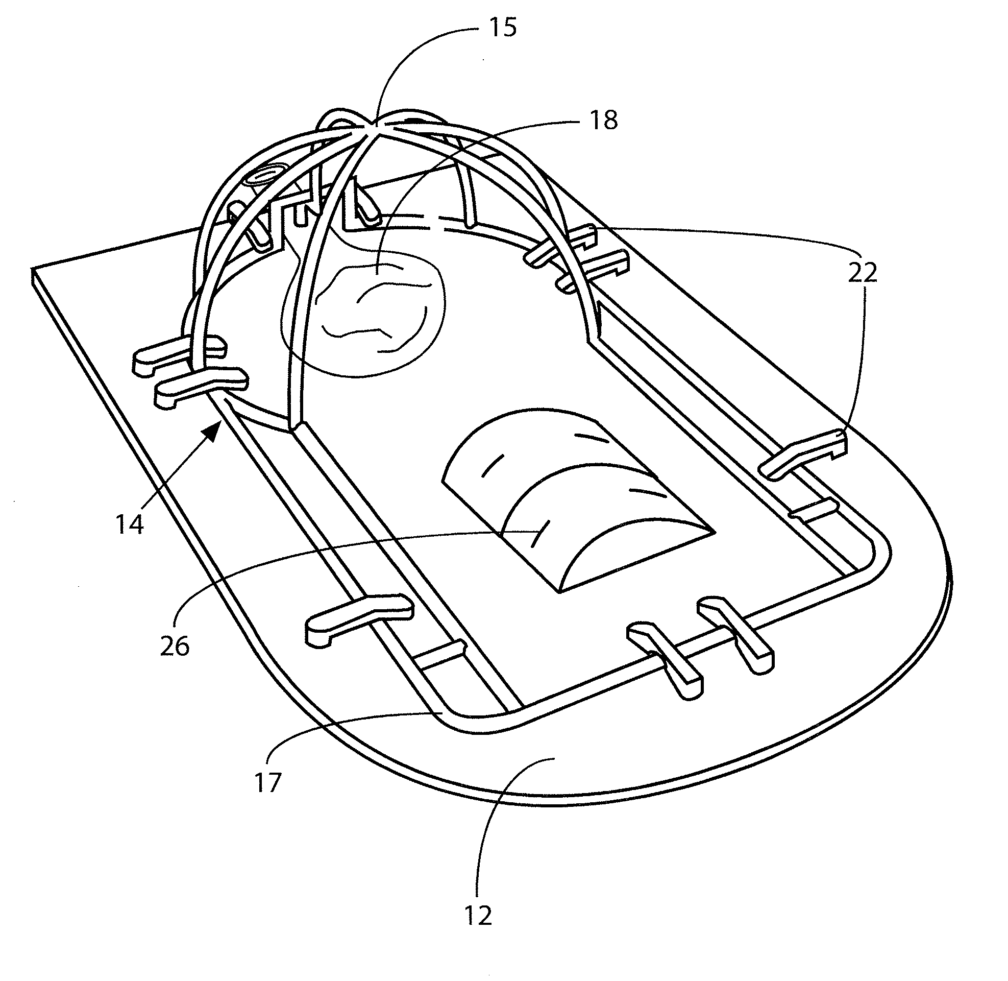
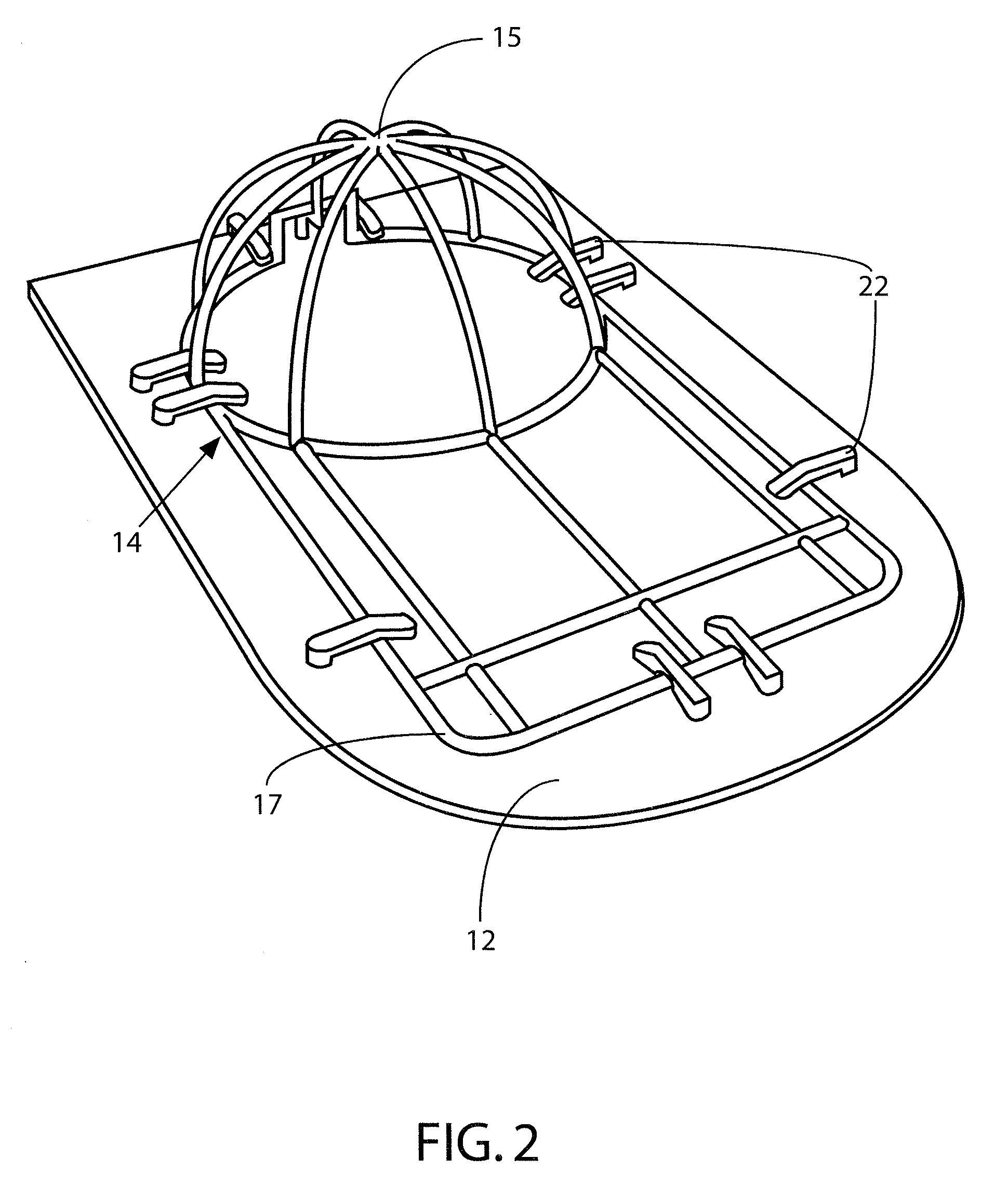
[0014]FIG. 2 provides a perspective view of the present invention assembled without a hat.

[0015]FIG. 3 provides a perspective view of an alternative embodiment of the present invention.

DETAILED DESCRIPTION OF A PRESENTLY PREFERRED AND VARIOUS ALTERNATIVE EMBODIMENTS OF THE INVENTION

[0016]Prior to proceeding to the more detailed description of the present invention it should be noted that, for the sake of clarity and understanding, identical components which have identical functions have been identified with identical reference numerals throughout the several views illustrated in the drawing figures.

[0017]Referring initially to FIG. 1, the apparatus, generally designated 10, of the present invention is shown in an exploded perspe...


PUM


Abstract

A cap drying and shaping apparatus includes a substantially planar base, an inflatable bladder disposed proximal one end of the planar base, and a ribbed cage member. The ribbed cage member includes a domed portion having a predetermined radius to the apex and a predetermined diameter parallel to the planar base, and a planar portion at least as long and wide as a bill on a typical ball cap. Attachment means are disposed on top of the planar base for removably clamping the ribbed cage member to the planar base.

Description

CROSS REFERENCE TO RELATED APPLICATION[0001]This patent application is related to and claims priority from U.S. Provisional Patent Application Ser. No. 61 / 016,709 filed Dec. 26, 2007.FIELD OF THE INVENTION[0002]The present invention relates, in general, to drying headgear and, more particularly, this invention relates to holding the shape of ball caps while drying and storing them.BACKGROUND OF THE INVENTION[0003]Prior to the conception and development of the present invention, hat and cap owners have sought ways to dry their headgear after laundering or getting it wet while still retaining the shape of the hat or cap. Wrinkles can easily appear during drying or even normal storage.[0004]Over many years, numerous devices have been proposed for preserving the shape of hats or caps during storage and / or drying. Inflatable hat blocks have been disclosed in U.S. Pat. Nos. 716,251, 1,742,397, 2,129,720, and 2,536,913; however, these devices did not comprehend billed caps. In addition, th...

Claims


Application Information

Patent Timeline
Patent Type & Authority Applications(United States)
IPC IPC(8): A41H5/02D06C15/00A42C1/00
CPCD06F59/02A42B1/002
Inventor BRYANT, CARL E.
Owner BRYANT CARL E
Why Eureka
Try Eureka