Double-locking connector

a connector and locking technology, applied in the direction of pipes/joints/fittings, couplings, mechanical devices, etc., can solve the problem that the connector is generally insufficiently resistant to pulling out the endpi

Inactive Publication Date: 2009-07-02
LEGRIS
View PDF5 Cites 4 Cited by
  • Summary
  • Abstract
  • Description
  • Claims
  • Application Information

AI Technical Summary

Benefits of technology

[0011]Thus, in the engaged position the locking member prevents the jumper from moving, so the jumper is thereby maintained in a positive manner in its retaining position.

Problems solved by technology

This means that such connectors are generally insufficiently resistant to pull-out of the endpiece when under high stress in applications such as when the pressure of the transported fluid is high and when the connector and the endpiece are subjected to high mechanical stresses.

Method used


Image

  • Double-locking connector
  • Double-locking connector
  • Double-locking connector

Examples


Embodiment Construction

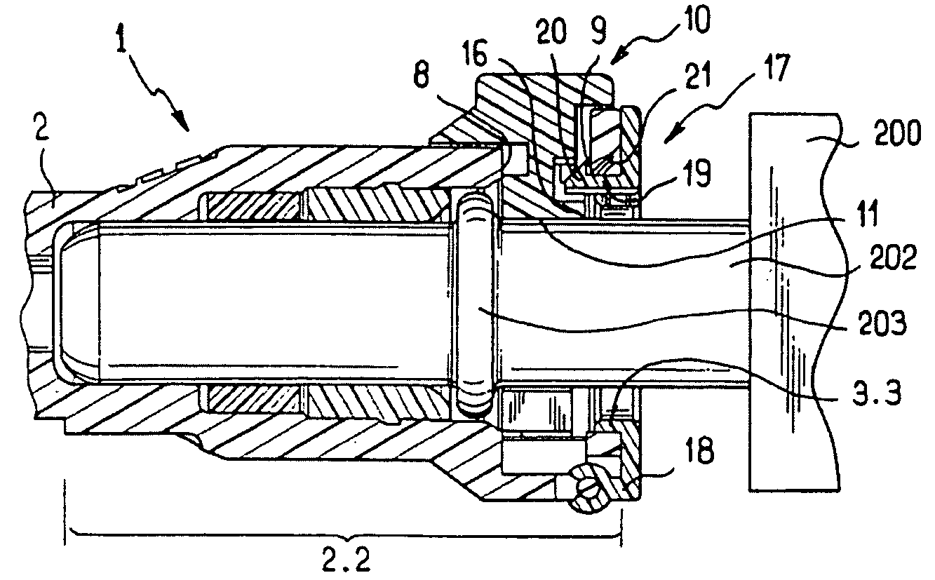
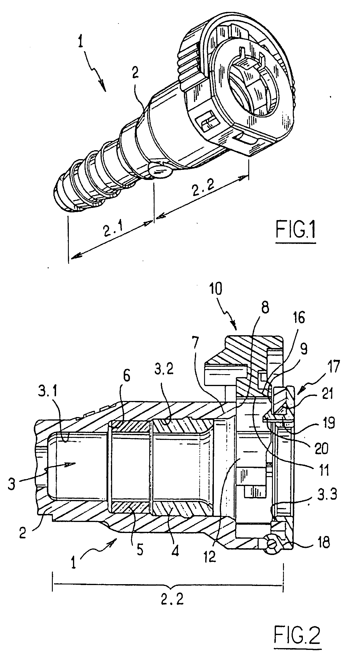
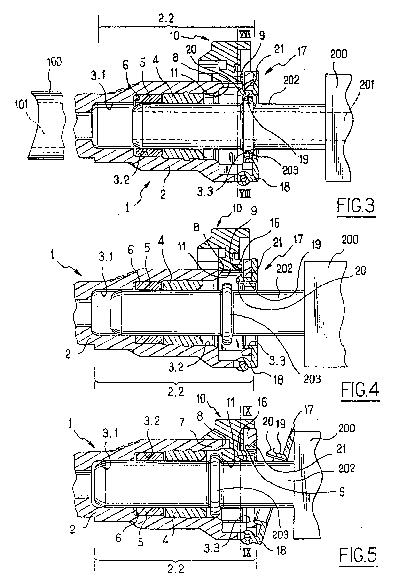
[0024]Referring to the figures, the connector of the invention, generally designated 1, is intended to connect a channel 101 of a circuit element 100 to a channel 201 of a circuit element 200 including a tubular endpiece 202 and provided with an external collar 203. The circuit element 100 here is a pipe. The circuit element 200 here is an element for supplying or receiving fluid the endpiece 202 of which is fixed thereto.

[0025]The connector 1 comprises a body 2 that is tubular, divided axially into a first section 2.1 intended to be connected to a circuit element 100 and a second section 2.2 intended to be connected to the endpiece 202.

[0026]The section 2.1 here is provided with barbs having a fir tree shaped profile intended to be forcibly introduced into the channel 101 of the circuit element 100. The section 2.1 may have other shapes, and may, for example, have the form of a nipple, or it may be identical to the section 2.2, or it may incorporate instantaneous connection means, ...


PUM


Abstract

A connector for connecting a circuit element to a tubular endpiece has an external collar, the connector having a tubular body with means for connecting the tubular body to the circuit element and a housing to receive the endpiece. The housing has a sealing member and is defined by a wall pierced by a lateral opening, and receives a jumper that is movable transversely of the body between a projecting position for retaining the collar of the endpiece and a retracted position for releasing the collar. The body has a member for locking the jumper in the retaining position, the locking member being mounted on the body such that it is movable between a position which engages the jumper and a position which disengages the jumper.

Description

BACKGROUND OF THE INVENTION[0001]1. Field of the Invention[0002]The present invention relates to a connector for connecting a fluid transport circuit element to a tubular endpiece provided with an external collar. The circuit element may be a fluid supplying or receiving element such as a pump, a pipe, a tank, a valve, or an actuator, etc. The tubular endpiece may be associated with another circuit element like those mentioned above.[0003]2. Brief Discussion of the Related Art[0004]A connector generally comprises a tubular body comprising means for connecting it to the circuit element and a housing to receive the endpiece. The housing is provided with a sealing member and means for securing the endpiece in the housing. The securing means can be divided into two main groups, namely instantaneous connection means and non-instantaneous connection means.[0005]Instantaneous connection means generally include a latch mounted on the body to be radially movable between a position that proje...

Claims


Application Information

Patent Timeline
Patent Type & Authority Applications(United States)
IPC IPC(8): F16L37/084
CPCF16L2201/10F16L37/144
Inventor BLIVET, PHILIPPEPODER, PHILIPPELE QUERE, PHILIPPE
Owner LEGRIS
Why Eureka
Try Eureka