Configurable Battery End-of-Life Indicator

a battery and end-of-life indicator technology, applied in the field of monitoring and warning systems, can solve problems such as limited li

Active Publication Date: 2009-07-02
AT&T INTPROP I L P
View PDF26 Cites 16 Cited by
  • Summary
  • Abstract
  • Description
  • Claims
  • Application Information

AI Technical Summary

Problems solved by technology

Uninterruptible power supply (UPS) systems may be used to back up critical systems in t

Method used


Image

  • Configurable Battery End-of-Life Indicator
  • Configurable Battery End-of-Life Indicator
  • Configurable Battery End-of-Life Indicator

Examples


Embodiment Construction

)

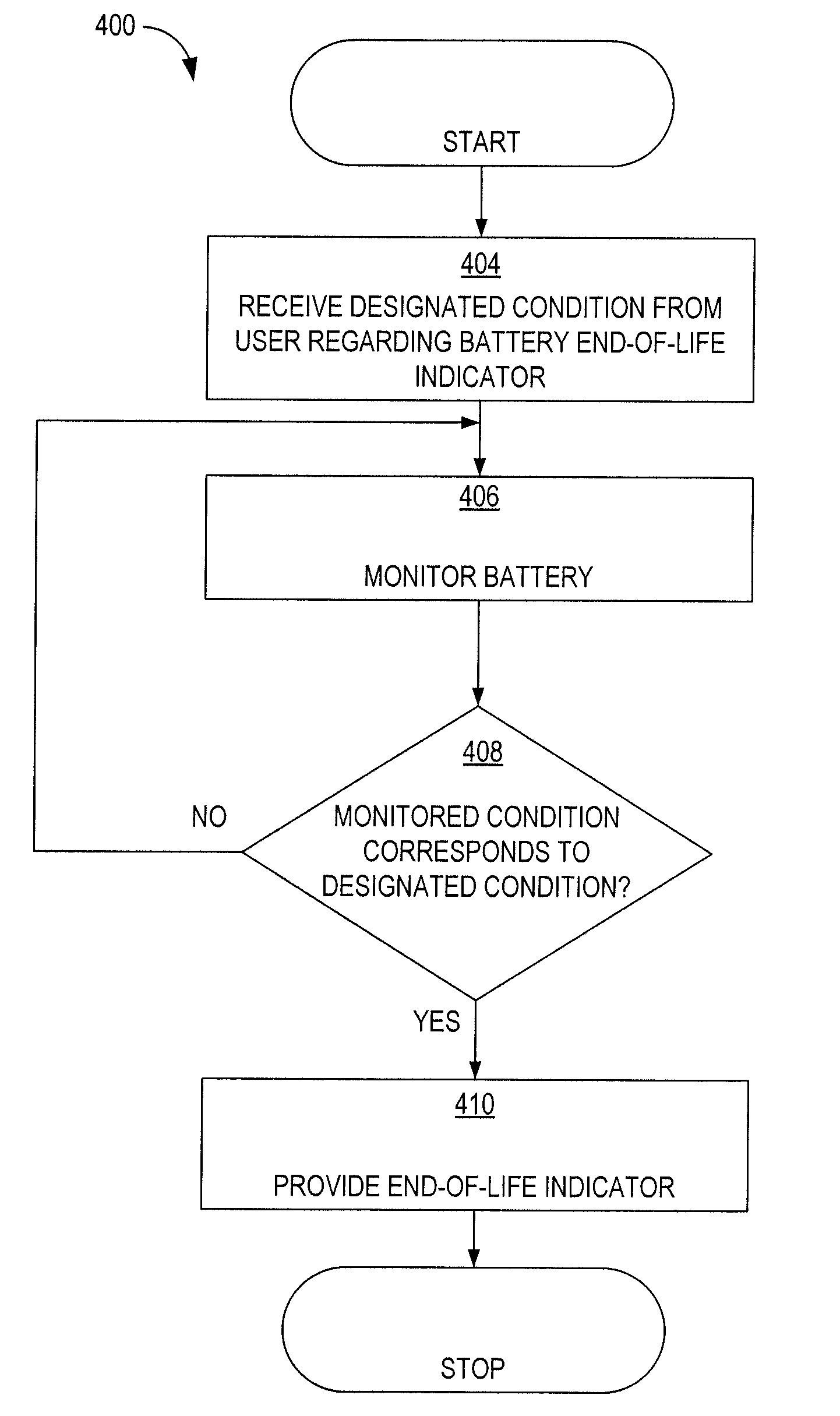
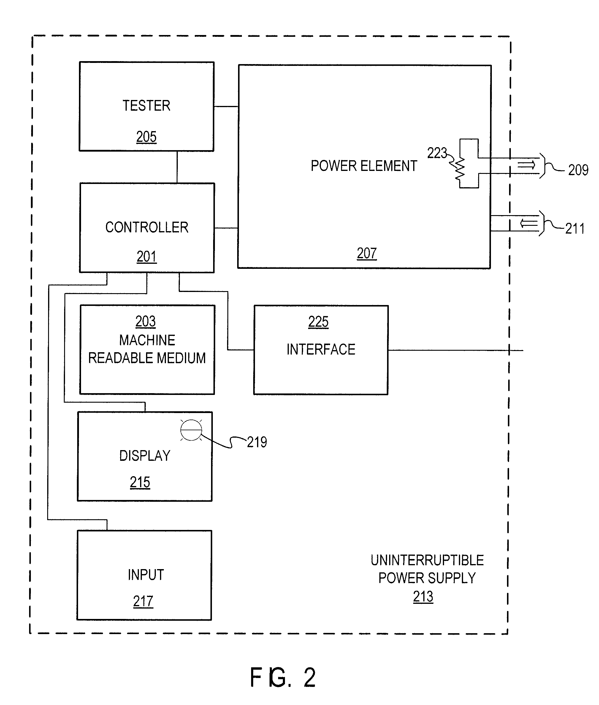
[0009]In one aspect, a UPS is disclosed which includes a tester for monitoring a performance characteristic of a power element. The UPS further includes an end-of-life indicator and an input for receiving an indicator of a designated condition under which the end-of-life indicator is activated. In addition, the UPS includes a controller for determining an end-of-life event based at least in part on the monitored performance characteristic and the received indicator. In some embodiments, the input of the UPS has a plurality of settings for specifying a requested period of operation for the power element during a power outage. The UPS may further include an interface for receiving the indicator of the designated condition. The controller may be enabled for measuring an output of the power element to estimate a load required of the power element during future operation. In some embodiments, the tester is enabled for monitoring performance of the power element by discharging the power ...


PUM


Abstract

A method, system, and computer program product are disclosed for providing end-of-life indicators for uninterruptible power supply (UPS) systems. User input is received regarding designated conditions for activating the end-of-life indicator. The UPS system monitors itself to determine whether monitored conditions correspond to the designating conditions. Upon the monitored conditions corresponding to the designating conditions, an audible or visible end-of-life indicator is activated. For critical systems, a user may specify conservative settings for the designated conditions. For other systems, a user may provide a designated condition (i.e., user input) that results in maximizing service life for the UPS system or associated batteries and reducing costs of ownership and operation.

Description

BACKGROUND[0001]1. Field of the Disclosure[0002]The present disclosure generally relates to monitoring and warning systems and in particular to end-of-life indicators for batteries.[0003]2. Description of the Related Art[0004]Uninterruptible power supply (UPS) systems may be used to back up critical systems in the event of power outages. UPS systems often rely on batteries that have a limited life. Systems for monitoring and alarming when a battery has reached its end-of-life often come from the battery manufacturer or the UPS system manufacturer in a fixed or pre-programmed configuration.BRIEF DESCRIPTION OF THE DRAWINGS[0005]FIG. 1 illustrates an example environment for operating a UPS system and for providing an associated end-of-life indicator;[0006]FIG. 2 depicts, in block diagram form, selected components of a UPS system;[0007]FIG. 3 illustrates an end-of-life indicator and adjustable input for use with a UPS system in accordance with disclosed embodiments; and[0008]FIG. 4 ill...

Claims


Application Information

Patent Timeline
IPC IPC(8): G08B21/00
CPCH02J9/06H02J7/0047H02J7/005G08B21/182
Inventor BI, HAIFENG
Owner AT&T INTPROP I L P
Why Eureka
Try Eureka