Vision system for vehicle

a technology for visualizing systems and vehicles, applied in television systems, identification means, instruments, etc., can solve problems such as devices that may stop communicating image signals, and achieve enhanced image displaying, enhanced image processing, and enhanced exterior scene image

Inactive Publication Date: 2011-02-01
DONNELLY CORP
View PDF115 Cites 537 Cited by
  • Summary
  • Abstract
  • Description
  • Claims
  • Application Information

AI Technical Summary

Benefits of technology

[0011]According to another aspect of the present invention, an imaging and display system or vision system may be operable in combination with or in conjunction with an auxiliary or triggering or initial sensing device or system or distance sensing / measuring / determining system. The auxiliary sensing device or system may provide additional sensing areas to cover blind spots that may not be encompassed by the imaging sensor or camera. Optionally, the auxiliary sensing system, such as ultrasonic sensors, radar, lidar, and the like, may detect an object exteriorly of the vehicle, and may determine or measure or detect the distance to the object, whereby the imaging and display system may be adjusted or controlled to provide enhanced imaging of the exterior scene or enhanced processing of the captured images or enhanced displaying of the images of the exterior scene and the detected object, in response to such an object detection by the auxiliary sensing system. For example, the imaging and display system may adjust a camera setting to provide enhanced imaging of the detected object, or may adjust the processor or control to provide enhanced processing of a portion of the image data that corresponds to the region of the scene at which the object was detected, or may adjust the display to highlight or enhance the displayed images of the detected object or of the region of the display that corresponds to the region of the exterior scene at which the object was detected.
[0012]Therefore, the present invention provides an imaging and display system or vision system that includes an imaging device and a display device connected via video connections or communication links. The imaging device includes user inputs and the imaging and display system is operable to selectively control or adjust the imaging device in response to the user inputs. The imaging and display system or vision system is operable to communicate imaging signals from the imaging device to the display device and to communicate camera control signals from the display device to the imaging device along common connections or wiring or communication links between the imaging device and the display device. The imaging and display system or vision system thus may provide various optional features or functions or modes without having to change or add wiring or connections between the imaging device and the display device.
[0017]Therefore, the present invention also provides an imaging system or vision system that includes an imaging sensor and a control that are operable to provide multiple functions or control of multiple accessories or the like via selective capturing of image data and processing of the captured image data. The control is thus operable to selectively capture images and process image data to provide multiple functions or applications with a common image sensor and image processor. The imaging system may synchronize the settings of the image sensor with the processing techniques applied to the image data by the image processor, in order to perform and / or optimize two or more functions of the imaging system. The present invention thus provides a multi-tasking capability to an image sensor and image processor while providing enhanced capturing of the images and processing of the image data for the desired functions or applications.

Problems solved by technology

The display microcontroller may affect the image signal by disabling a video termination at the display device, and the imaging device may stop communicating the image signal when the video termination is disabled.

Method used


Image

  • Vision system for vehicle
  • Vision system for vehicle
  • Vision system for vehicle

Examples


Embodiment Construction

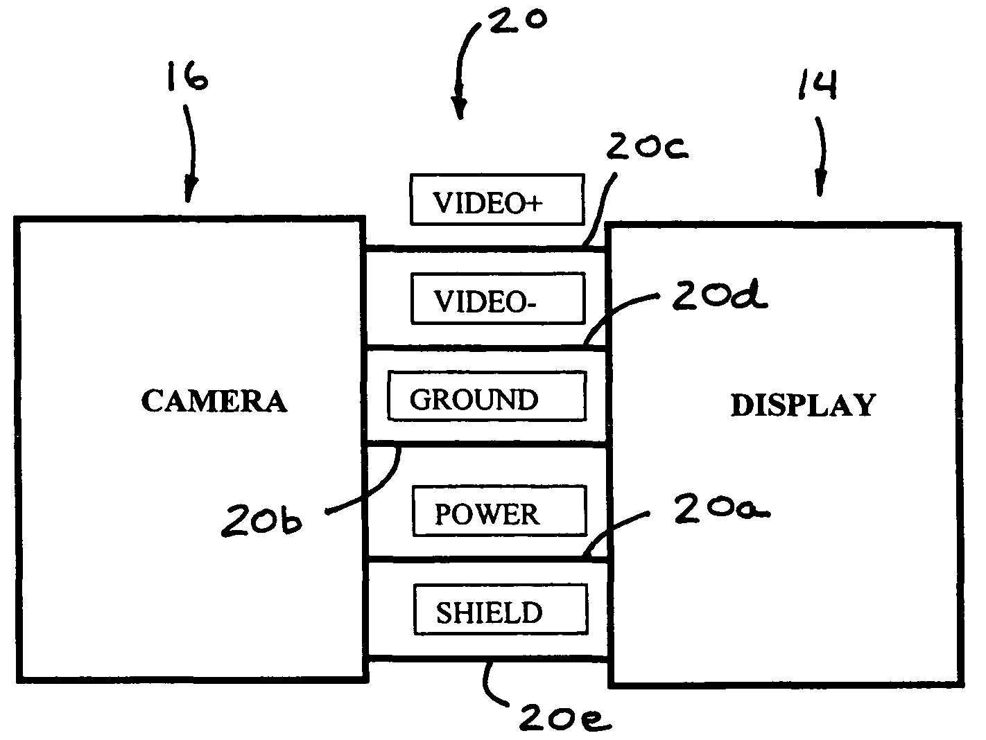
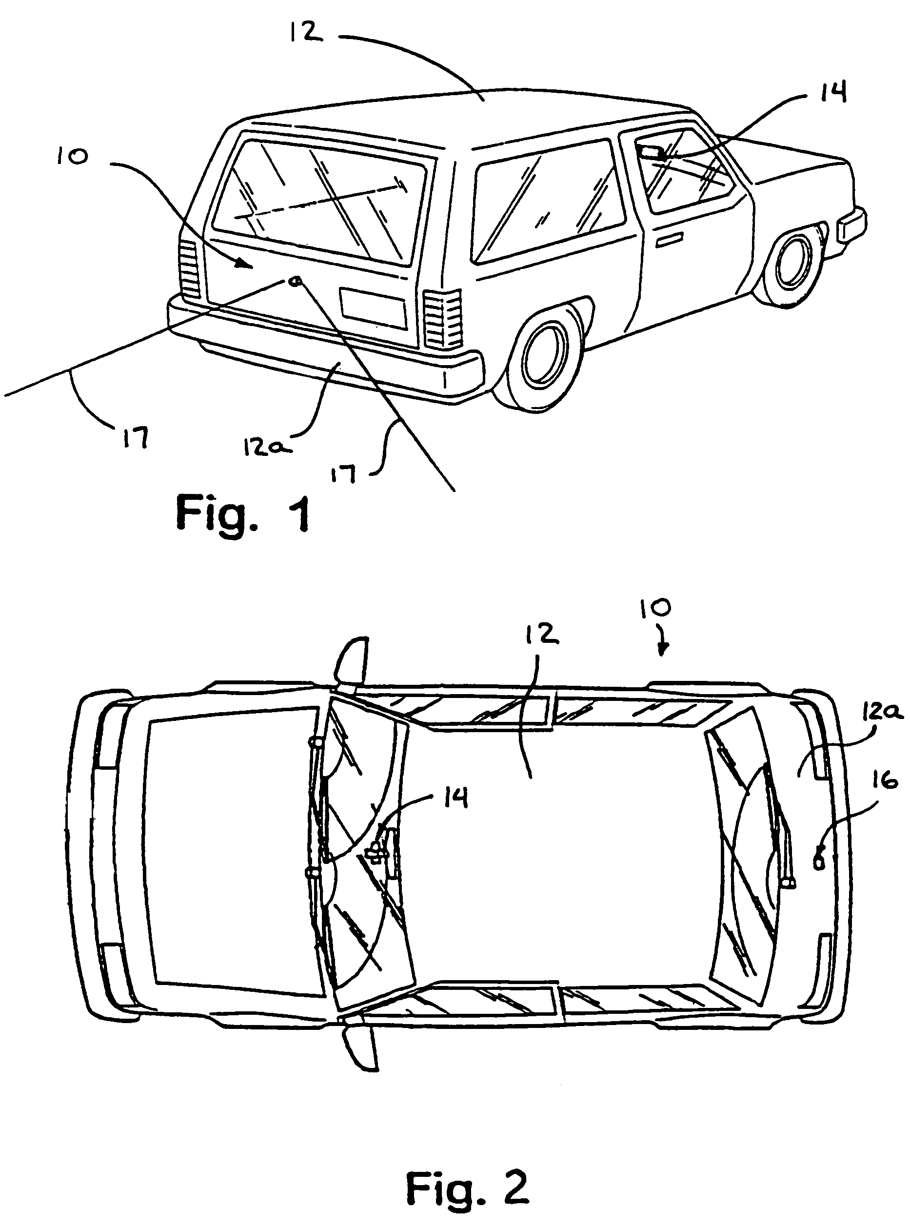
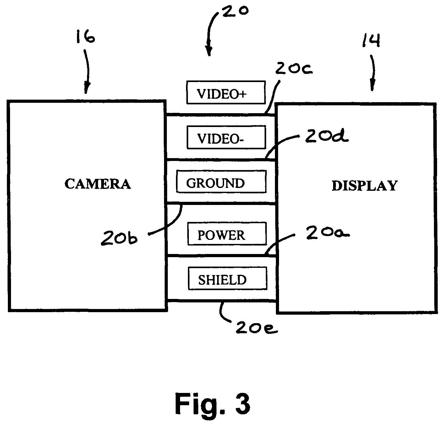
[0028]Referring now to the drawings and the illustrative embodiments depicted therein, an image capture system or vision system or imaging and display system 10 is positioned at an exterior portion 12a of a vehicle 12, such as at a rearward portion 12a of the vehicle 12, and is operable to capture an image of a scene occurring exteriorly of the vehicle, such as rearwardly of the vehicle, and to display the image at a display device or display system 14 of the vehicle which is viewable by a driver of the vehicle (FIGS. 1 and 2). Vision system 10 includes display device or system 14 and an imaging system or imaging device 16, which includes an imager or image capture device or camera 22 that is directed exteriorly of the vehicle and has an exterior field of view 17 which preferably at least partially encompasses a “blind spot” area exteriorly of the vehicle. The images or frames captured by imaging system 16 are displayed at a display element 28 of display system 14 to assist the driv...


PUM


Abstract

A vision system for a vehicle includes an imaging device having an imaging sensor, a camera microcontroller, a display device having a display element, a display microcontroller, and at least one user input selectively actuatable by a user. The imaging device communicates an image signal to the display device via a communication link. The display microcontroller affects the image signal in response to the at least one user input. The camera microcontroller monitors the image signal on the communication link and adjusts a function of the imaging device in response to a detection of the affected image signal. The vision system may adjust a display or sensor of the system in conjunction with a distance detecting system.

Description

CROSS REFERENCE TO RELATED APPLICATIONS[0001]The present application claims the benefit of U.S. provisional application Ser. No. 60 / 628,709, filed Nov. 17, 2004; and Ser. No. 60 / 614,644, filed Sep. 30, 2004, which are all hereby incorporated herein by reference in their entireties.FIELD OF THE INVENTION[0002]The present invention relates to imaging systems for vehicles and, more particularly, to reverse aid imaging systems with a rearward facing imaging device or camera and a display. However, aspects of the present invention are equally suitable for other vehicle imaging systems, such as side object detection systems, and forward facing imaging systems and the like.BACKGROUND OF THE INVENTION[0003]The advent of low cost, reliable imaging devices, based on a variety of silicon technologies, and in particular CMOS technology, combined with an improved cost / performance ratio for displays capable of meeting automotive specifications, and an increasing application rate of video monitor ...

Claims


Application Information

Patent Timeline
Patent Type & Authority Patents(United States)
IPC IPC(8): G06K9/00
CPCB60R1/00G06K9/00791G08G1/16G08G1/167H04N7/185H04N7/188Y10S348/904B60R2300/101B60R2300/106B60R2300/301B60R2300/302B60R2300/304B60R2300/305B60R2300/802B60R2300/804B60R2300/8053B60R2300/8066B60R2001/1253G08G1/165G06V20/56G06V20/588G06V20/584G06V20/58G08G1/166H04N7/183
Inventor CAMILLERI, JOSEPHGIBSON, JOEL S.SCHOFIELD, KENNETH
Owner DONNELLY CORP
Why Eureka
Try Eureka