Light-emitting diode based products

a technology of light-emitting diodes and products, applied in the field of light-emitting diodes based products, can solve the problems of limited accessories, limited application range, and limited range of illuminated systems, and achieve the effect of addressing the application of programmable, multi-colored lighting systems

Inactive Publication Date: 2006-06-20
PHILIPS LIGHTING NORTH AMERICA CORPORATION
View PDF416 Cites 533 Cited by
  • Summary
  • Abstract
  • Description
  • Claims
  • Application Information

AI Technical Summary

Benefits of technology

[0025]High-brightness LEDs, combined with a processor for control, can produce a variety of pleasing effects for display and illumination. A system disclosed herein uses high-brightness, processor-controlled LEDs in combination with diffuse materials to produce color-changing effects. The systems described herein may be usefully employed to bring autonomous color-changing ability and effects to a variety of consumer products and other household items. The system may also include sensors so that the illumination of the LEDs might change in response to environmental conditions or a user input. Additionally, the system may include an interface to a network, so that the illumination of the LEDs may be controlled via the network.

Problems solved by technology

Existing illuminated systems, however, are generally only capable of exhibiting fixed illumination with one or more light sources.
Such accessories, however, remain limited to a small number of different colored states, for example, three distinct illumination colors: red (red bulb illuminated); blue (blue bulb illuminated); and purple (both red and blue bulbs illuminated).
While these references teach systems for producing lighting effects, they do not address some applications of programmable, multi-colored lighting systems.
There are toy balls that have lighted parts or balls where the entire surface appears to glow, however there is no ball available that employs dynamic color changing effects.
Moreover, there is no ball available that responds to data signals provided from a remote source.
As a significant disadvantage, these systems employ complicated wiring harnesses to achieve dynamic lighting.

Method used


Image

  • Light-emitting diode based products
  • Light-emitting diode based products
  • Light-emitting diode based products

Examples


Embodiment Construction

)

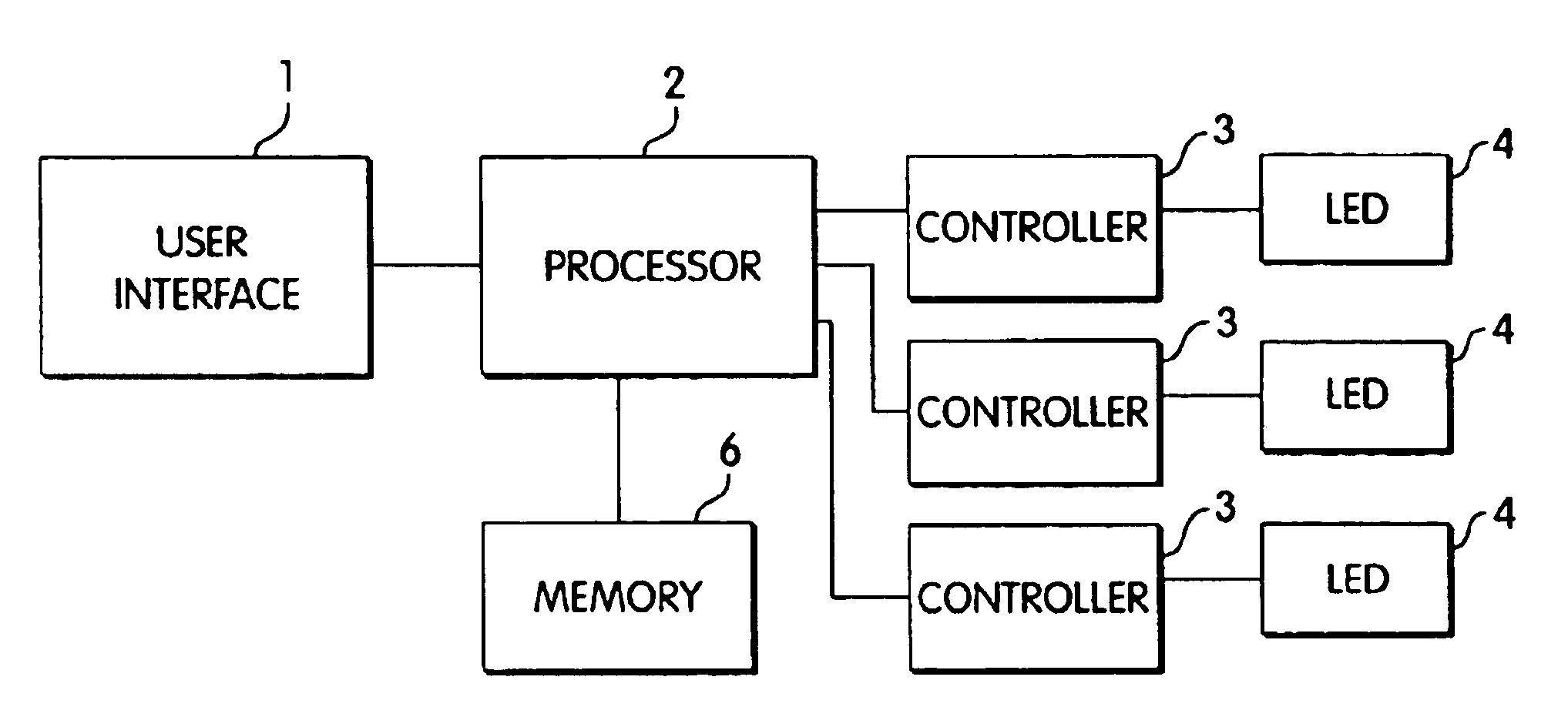
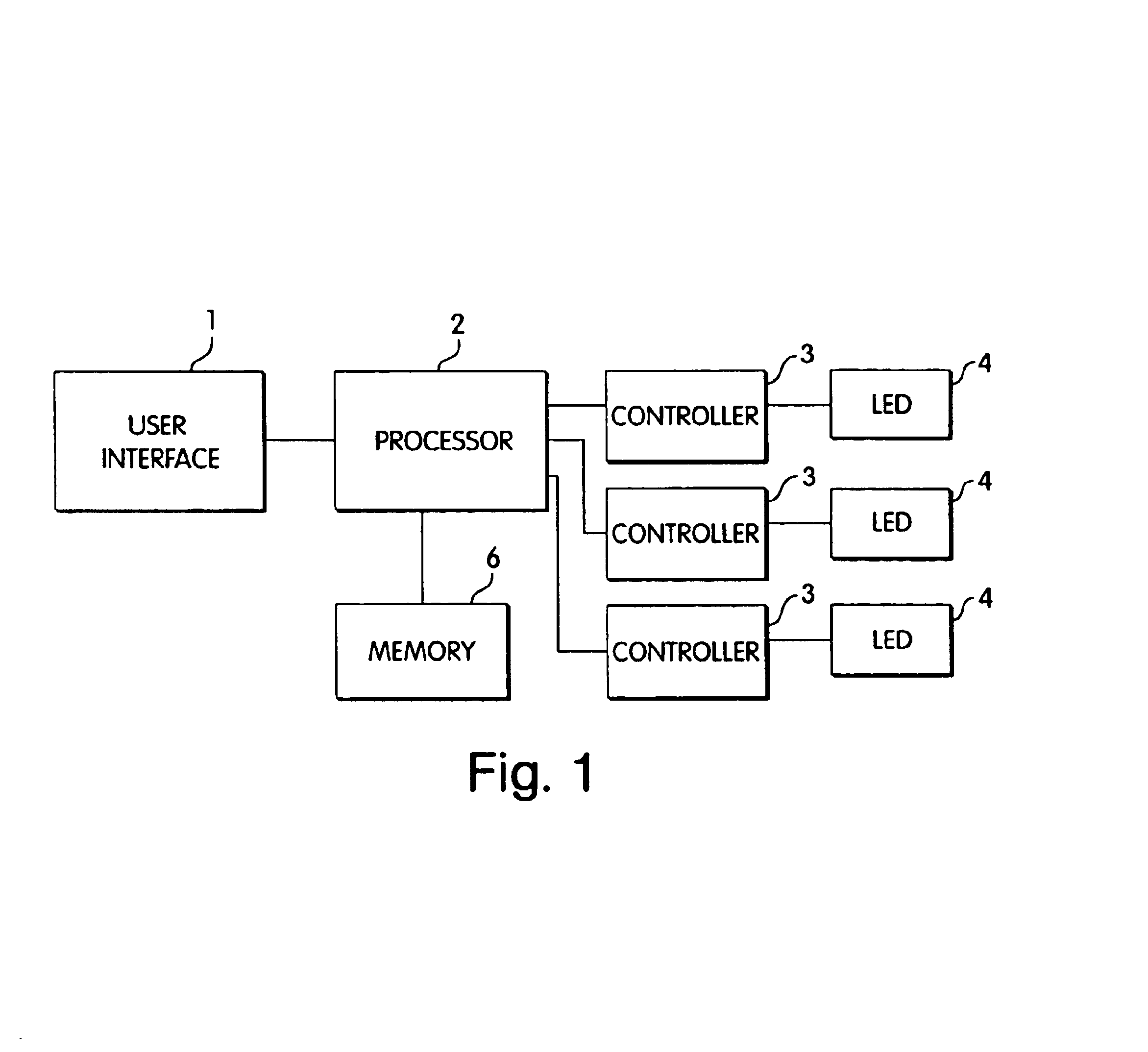
[0054]To provide an overall understanding of the invention, certain illustrative embodiments will now be described, including various applications for programmable LED's. However, it will be understood by those of ordinary skill in the art that the methods and systems described herein may be suitably adapted to other environments where programmable lighting may be desired, and that some of the embodiments described herein may be suitable to non-LED based lighting.

[0055]As used herein, the term “LED” means any system that is capable of receiving an electrical signal and producing a color of light in response to the signal. Thus, the term “LED” should be understood to include light emitting diodes of all types, light emitting polymers, semiconductor dies that produce light in response to current, organic LEDs, electro-luminescent strips, silicon based structures that emit light, and other such systems. In an embodiment, an “LED” may refer to a single light emitting diode package havi...


PUM


Abstract

High-brightness LEDs, combined with a processor for control, can produce a variety of pleasing effects for display and illumination. A system disclosed herein uses high-brightness, processor-controlled LEDs in combination with diffuse materials to produce color-changing effects. The systems described herein may be usefully employed to bring autonomous color-changing ability and effects to a variety of consumer products and other household items. The system may also include sensors so that the illumination of the LEDs might change in response to environmental conditions or a user input. Additionally, the system may include an interface to a network, so that the illumination of the LEDs may be controlled via the network.

Description

CROSS REFERENCE TO RELATED APPLICATIONS[0001]This application claims the benefit, under 35 U.S.C. §119(e), of the entire disclosure of the following United States provisional patent applications (each of which is incorporated herein by reference):[0002]U.S. Provisional Patent App. No. 60 / 199,333, filed Apr. 24, 2000; and[0003]U.S. Provisional Patent App. No. 60 / 211,417, filed Jun. 14, 2000.[0004]This application also claims the benefit as a continuation-in-part of the following United States patent applications:[0005]U.S. patent application Ser. No. 09 / 215,624, filed Dec. 17, 1998 now U.S. Pat. No. 6,528,954, which is incorporated herein by reference and which claims the benefit of the following provisional applications:[0006]Ser. No. 60 / 071,281, filed Dec. 17, 1997, entitled “Digitally Controlled Light Emitting Diodes Systems and Methods”;[0007]Ser. No. 60 / 068,792, filed Dec. 24, 1997, entitled “Multi-Color Intelligent Lighting”;[0008]Ser. No. 60 / 078,861, filed Mar. 20, 1998, entit...

Claims


Application Information

Patent Timeline
Patent Type & Authority Patents(United States)
IPC IPC(8): G05F1/00F21V33/00F21K99/00H05B37/02H05B44/00
CPCA61N5/0616F21K9/00H05B33/0803H05B33/0827H05B33/0857H05B33/0863H05B33/0872H05B37/0254H05B37/029F21K9/13A61N5/0618F21V23/045A61N2005/0652F21S4/008F21V33/004F21V33/006F21W2111/027F21W2111/08F21Y2101/02F21Y2103/003F21S4/28F21K9/23F21Y2103/10F21Y2115/10H05B47/155H05B45/20H05B47/175H05B45/46H05B47/18H05B45/325H05B45/33H05B45/3577H05B45/3578H05B45/28
Inventor DOWLING, KEVIN J.MORGAN, FREDERICK M.LYS, IHOR A.BLACKWELL, MICHAEL K.DUCHARME, ALFREDOSTERHOUT, RALPHPIEPGRAS, COLINMUELLER, GEORGE C.GEARY, DAWN
Owner PHILIPS LIGHTING NORTH AMERICA CORPORATION
Why Eureka
Try Eureka