Control device for servo die cushion
a control device and servo die technology, applied in the direction of electric programme control, program control, instruments, etc., can solve the problems of not being able to achieve expected machining, the amount of pressure cannot be varied in the and the control of a hydraulic or pneumatic unit can only be carried out under constant pressure. , to achieve the effect of pressing for
- Summary
- Abstract
- Description
- Claims
- Application Information
AI Technical Summary
Benefits of technology
Problems solved by technology
Method used
Image
Examples
first embodiment
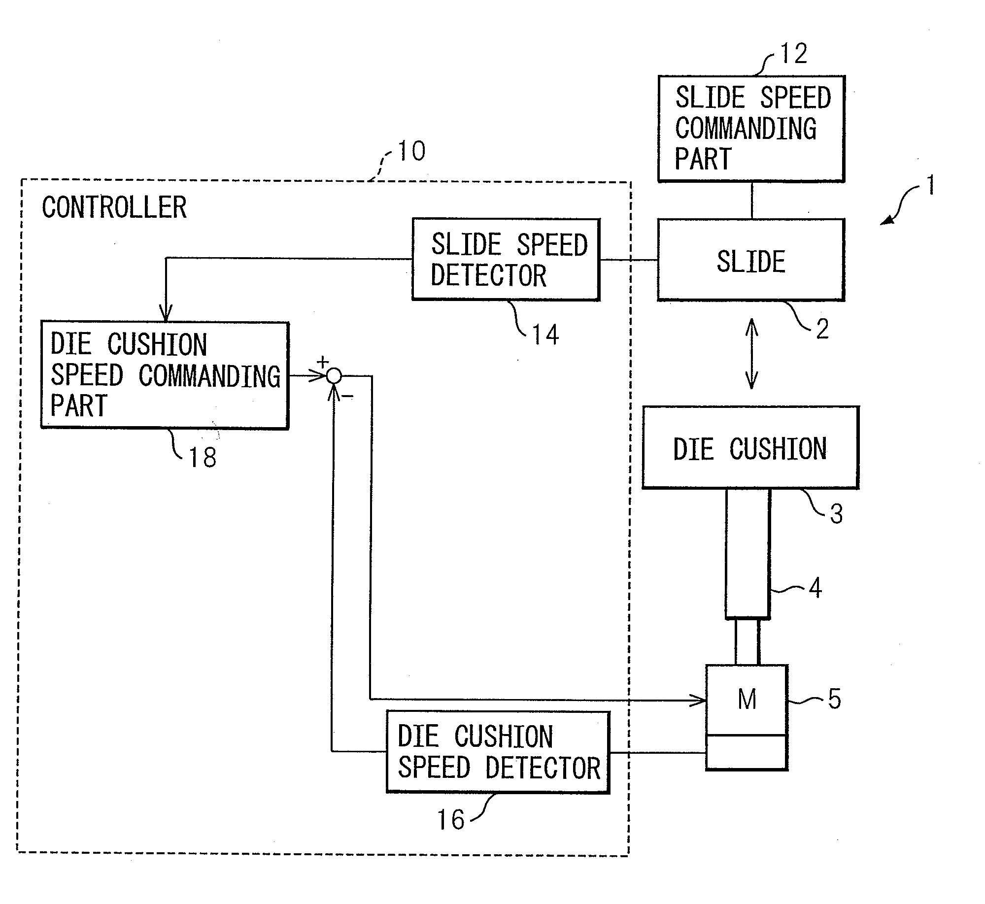
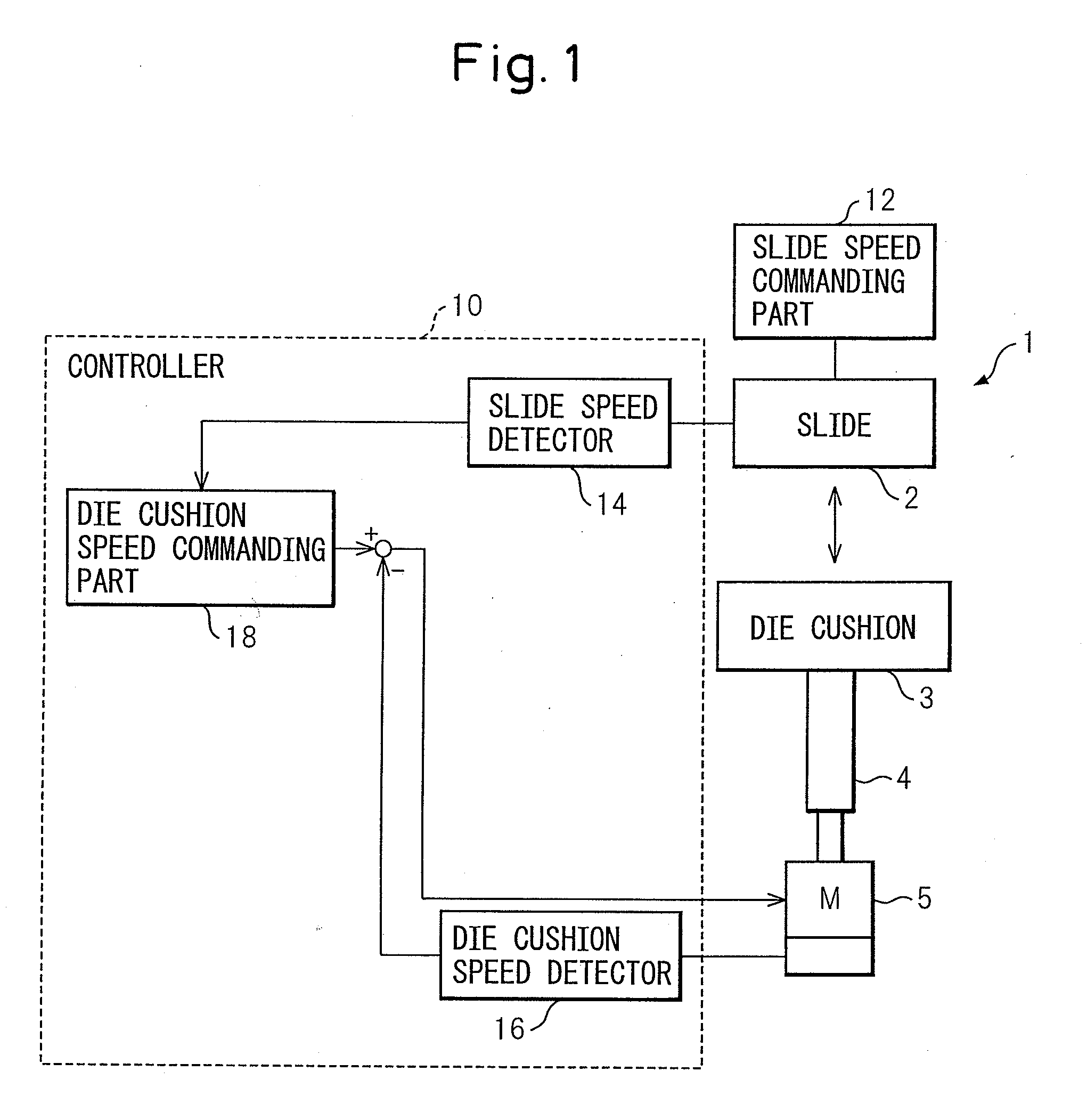
[0036]FIG. 1 shows a schematic configuration of a press machine 1 including a control device or controller 10 for a servo die cushion according to the invention. The press machine 1 includes a slide 2 driven by a link mechanism or the like (not shown) and a die cushion 3 configured to move corresponding to the motion of the slide 2. The position of die cushion 3 is sequentially controlled (in other words, the speed of the die cushion is controlled) by a servomotor 5 via a ball screw 4. The slide 2 may be controlled based on a command from a slide speed commanding part 12. The controller 10 for controlling the servomotor 5 includes a slide speed detecting part or a slide speed detector 14 for detecting the speed of the slide 2, a die cushion speed detecting part or a die cushion speed detector 16 for detecting the speed of the die cushion 3, and a die cushion speed commanding part 18 for generating a speed command of the die cushion 3.
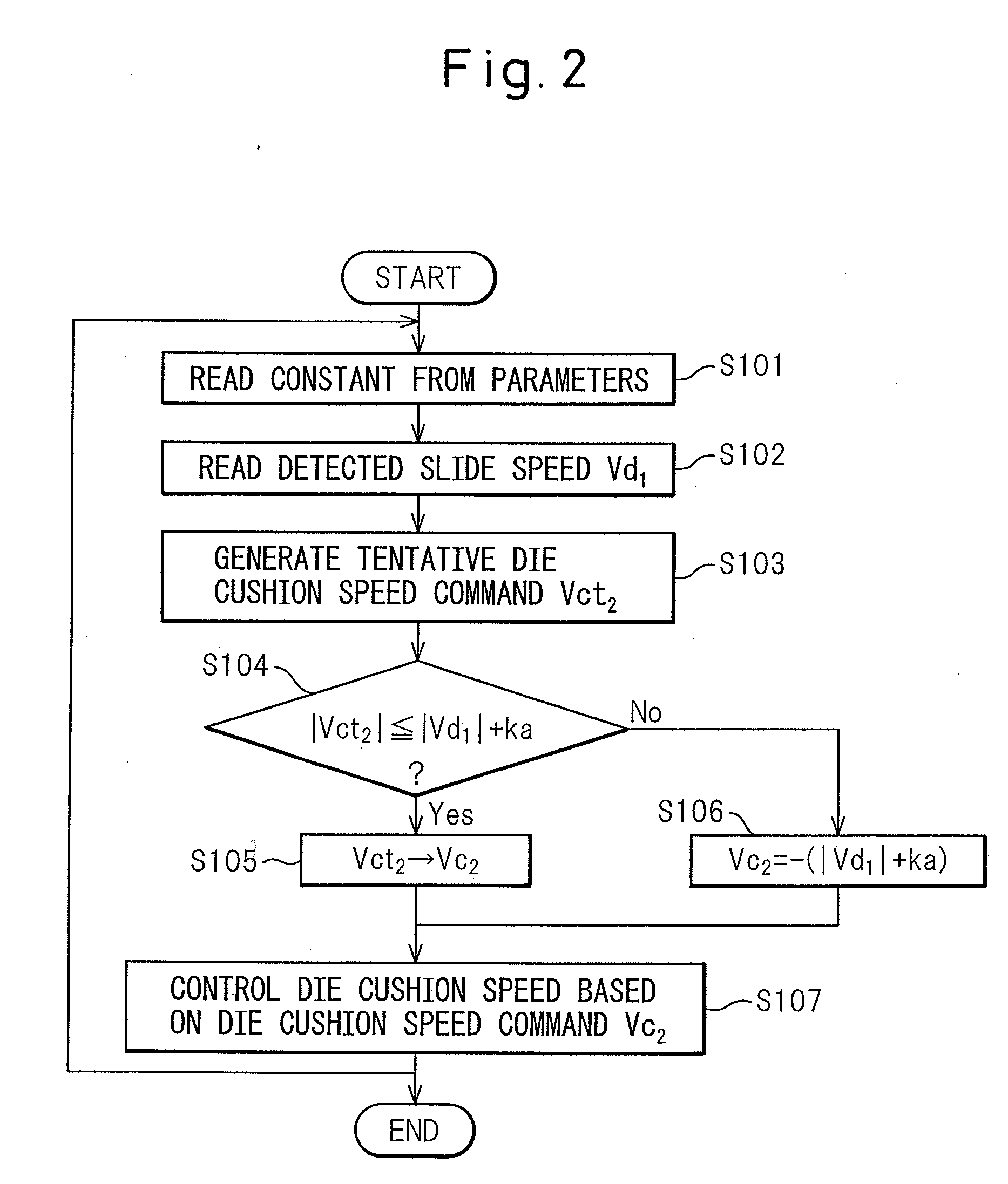
[0037]FIG. 2 is a flowchart indicating a procedur...
second embodiment
[0042]As described with reference to FIG. 14, the period of time, in which the detected force is significantly smaller than the desired command force, typically occurs just after the collision between the slide and the die cushion. Therefore, when a certain time has passed just after the collision, the above problem is not caused even if the control is performed focusing on setting the force error to zero after the collision as in the prior art. Accordingly, in a second embodiment as described below, a technique for specifying a period of time in which the speed command of the die cushion is limited.
[0043]FIG. 6 shows a schematic configuration of a press machine 1 including a control device or a controller 10a for a servo die cushion according to a second embodiment of the invention. The controller 10a includes a collision detecting part or detector 20 and a counter 22 for counting elapsed time after the detection by the detector 20, as well as the components of the controller 10 of...
third embodiment
[0046]In a third embodiment as described below, the command speed of the die cushion is limited by using the above equations, with the slide speed in equation (1) or (2) being multiplied by a constant smaller than one.
[0047]FIG. 8 shows a schematic configuration of a press machine 1 including a control device or a controller 10b for a servo die cushion according to a third embodiment of the invention. The press machine 1 further includes a force detecting part or detector 24 for detecting a force applied to the die cushion 3 by means of the slide 2, and a force commanding part 26 for commanding a force to be generated between the slide 2 and the die cushion 3. The die cushion speed commanding part 18 includes a force gain 28 for calculating a tentative speed command based on a force error (or a value obtained by subtracting a detected force by the force detector 24 from a command force by the force commanding part 26).
[0048]FIG. 9 is a flowchart showing a procedure of the controller...
PUM
| Property | Measurement | Unit |
|---|---|---|
| force | aaaaa | aaaaa |
| speed | aaaaa | aaaaa |
| threshold | aaaaa | aaaaa |
Abstract
Description
Claims
Application Information
 - R&D
- Intellectual Property
- Life Sciences
- Materials
- Tech Scout
- Unparalleled Data Quality
- Higher Quality Content
- 60% Fewer Hallucinations
Browse by: Latest US Patents, China's latest patents, Technical Efficacy Thesaurus, Application Domain, Technology Topic, Popular Technical Reports.
© 2025 PatSnap. All rights reserved.Legal|Privacy policy|Modern Slavery Act Transparency Statement|Sitemap|About US| Contact US: help@patsnap.com


