
Lenticular lens sheet

a technology of lenticular lens and lens top portion, applied in the field of lenticular lens sheet, can solve the problems of rubbing occurrence of a gap between the lens sheets, and rubbing was particularly likely to occur, so as to reduce the scraping of the fresnel lens top portion, the pressing force between the two lens sheets can be made high, and the effect of preventing the scraping

Inactive Publication Date: 2002-03-19
KURARAY CO LTD
View PDF11 Cites 7 Cited by
  • Summary
  • Abstract
  • Description
  • Claims
  • Application Information

AI Technical Summary

Benefits of technology

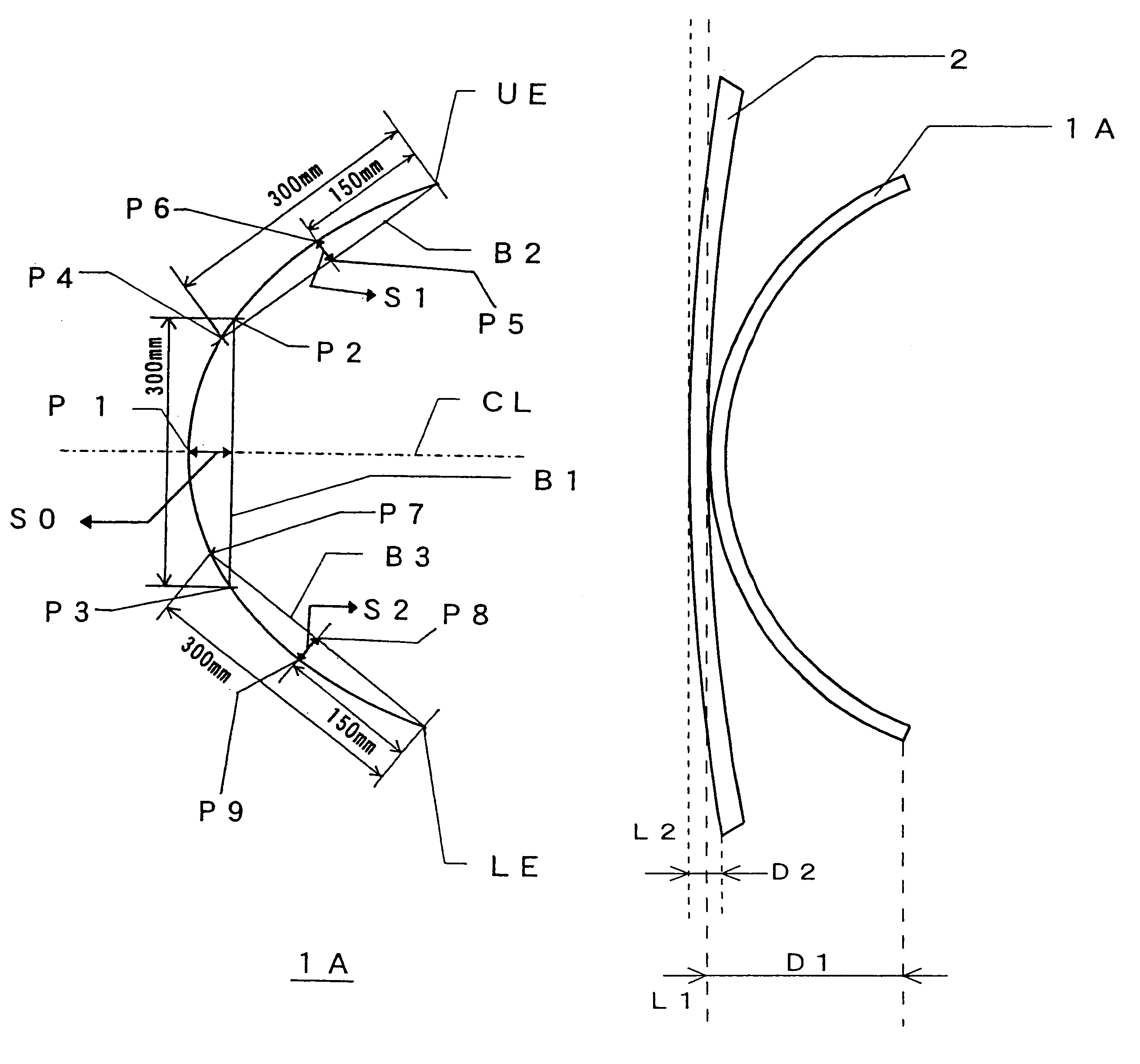
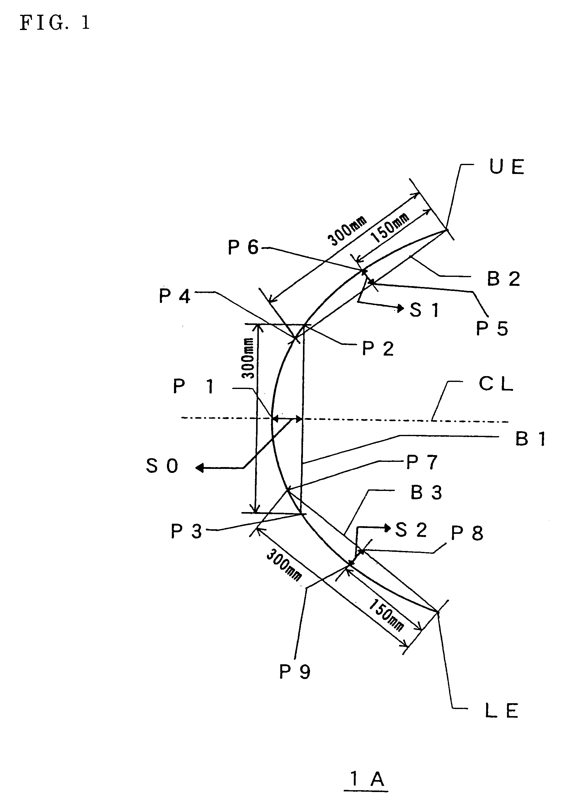
When a lenticular lens sheet and Fresnel lens sheet are combined as a screen, as shown in FIG. 4, their upper edges and lower edges are fixed to and supported by a screen frame 6. With the lenticular lens sheet of the present invention, in which the warping (S1, S2) nearer the upper and lower edges is smaller than the warping (S0) in the middle region of the lenticular lens sheet, the pressing force acting at the points of contact between the lenticular lens sheet surface and the Fresnel lens sheet surface in the vicinity of the screen frame at the upper and lower edges can be lowered, making it possible to suppress scraping of the Fresnel lens top portions occurring in this region. Also, in the vicinity of the center of the lens sheet, where a gap may easily occur between the lenticular lens sheet and Fresnel lens sheet, the pressing force between the two lens sheets can be made high, so occurrence of gaps between the lenticular lens sheets and Fresnel lens sheets is infrequent, just as in the case where flat lenticular lens sheets are employed to which warping is not applied.

Problems solved by technology

The magnitude of elongation and contraction of the lens sheets in response to ambient temperature / humidity changes is different, and this may therefore result in the occurrence of a gap between the lens sheets.
When such lens sheets to which warping has been applied are assembled in a television set using a screen in which they are fixed in a frame, and this is transported by being loaded onto for example a truck, rubbing may occur between the two lens sheets due to vibration etc during transportation.
Rubbing was particularly likely to occur at the upper and lower edges of the screen, where scraping off of the top portions of the Fresnel lens or the lenticular lens could severely impair image quality.
Typically, therefore the width of the flat part which was provided was only a few .mu.m, which was insufficient to offer the benefit of preventing scraping due to rubbing of the two lens sheets.
Consequently, it is not possible to provide the flat parts of the Fresnel lens top portions selectively exclusively in the vicinity of the upper and lower edges of the screen, and even regions in the vicinity of the center line (height direction) of the lens sheet offset towards the left and right edges, where flat parts of the Fresnel lens top portions are basically unnecessary, must be machined; there was thus the problem that considerable time was required for machining of the metal mold.
It was therefore not possible to solve simultaneously the problems of eliminating a gap between the lenticular lens sheet and Fresnel lens sheet and of preventing scraping due to rubbing of the two lens sheets.

Method used


Image

  • Lenticular lens sheet
  • Lenticular lens sheet
  • Lenticular lens sheet

Examples


working examples

Example 1

Warping was applied to a Fresnel lens sheet manufactured by forming a Fresnel lens pattern on a sheet of thickness 2 mm made of acrylic-styrene copolymer resin by the method of photopolymerization using a UV-hardening resin, such that the image light input side was convex (the magnitude of the convex warping of the Fresnel lens sheet (D2 in FIG. 3) was 10 mm). A lenticular lens sheet having warping of S0 of 14.7 mm, S1 and S2 of 9.2 mm as defined above was manufactured by inserting a lenticular lens sheet of thickness 0.9 mm made of acrylic resin into a warping mold and heating.

When a Fresnel lens sheet and lenticular lens sheet as described above were set in position in the frame of a television set such that the face that was formed with the Fresnel lens was on the side of the lenticular lens sheet, and a long-distance transportation test was conducted in which this was loaded on to a truck and transported for about 1000 km, no scraping of the Fresnel lens top portions or...

example 2

A lenticular lens sheet having warping of S0 of 9.0 mm, Si and S2 of 7.5 mm as defined above was manufactured by inserting a lenticular lens sheet of thickness 0.9 mm made of acrylic resin into a warping mold different from that of Example 1 and heating. When this lenticular lens sheet was set in position in the frame of a television set together with a Fresnel lens sheet identical with that of Example 1, the face where the Fresnel lens shape was formed being on the side of the lenticular lens sheet, and a long-distance transportation test and high-temperature high-humidity test were conducted in the same way as in Example 1, in each case excellent results were obtained just as in Example 1.

example 3

A lenticular lens sheet having warping of S0 of 22.0 mm, S1 and S2 of 17.0 mm as defined above was manufactured by inserting a lenticular lens sheet of thickness 0.9 mm made of acrylic resin into a warping mold different from that of Examples 1 and 2 and heating. When this lenticular lens sheet was set in position in the frame of a television set together with a Fresnel lens sheet identical with that of Examples 1 and 2, the face where the Fresnel lens shape was formed being on the side of the lenticular lens sheet, and a long-distance transportation test and high-temperature high-humidity test were conducted in the same way as in Examples 1 and 2, in each case excellent results were obtained just as in Examples 1 and 2.


PUM


Abstract

A lenticular lens sheet has arcuate-shaped warping such that the optical output lens side is the concave side, where, considering a chord B1 that connects points P2 and P3 to each other which are points on this approximate curve of arcurate shape and are of distance 150 mm from center line CL, and between which a distance is 300 mm, a distance to this chord B1 from the point P1 where this approximate curve and this center line intersect is represented by S0, and, considering a chord B2 that connects an upper edge UE of this approximate curve to a point P4 300 mm from the upper edge in the downwards direction, a distance to this chord B2 from the point P6 where the perpendicular from the central point P5 of this chord B2 intersects this approximate curve is represented by S1, and, considering a chord B3 that connects a lower edge LE of this approximate curve to a point P7 300 mm from the lower edge in the upwards direction, a distance to this chord B3 from the point P9 where the perpendicular from the central point P8 of this chord B3 intersects this approximate curve is represented by S2, respectively, there exists a relationship satisfying S0>S1>0 and S0>S2>0.

Description

TECHNICAL FIELDThe present invention relates to a lenticular lens sheet used in the screen of for example rear projection type television sets.BACKGROUND ARTConventionally, as the screen of a rear projection type television set, a combination of a lenticular lens sheet and a Fresnel lens sheet is known. In such screens, two or more lens sheets made of plastics of different thickness and material are combined. The magnitude of elongation and contraction of the lens sheets in response to ambient temperature / humidity changes is different, and this may therefore result in the occurrence of a gap between the lens sheets. Accordingly, as shown in FIG. 5, occurrence of a gap between the lens sheets is prevented by causing the two lens sheets to adhere by utilizing the resilience of the lens sheets, by applying warping to the lenticular lens sheet and Fresnel lens sheet such that the degree of warping is more gentle in the case of the Fresnel lens sheet 2 than in the case of the lenticular ...

Claims


Application Information

Patent Timeline
Patent Type & Authority Patents(United States)
IPC IPC(8): G03B21/62G03B21/625
CPCG03B21/625G02B3/005G02B3/08G03B21/58H04N9/3141
Inventor YOSHIMURA, OSAMU
Owner KURARAY CO LTD
Learn More