Roller burnishing apparatus with pressing-force detecting device

a technology of pressing force detection and burnishing apparatus, which is applied in the direction of grinding/polishing apparatus, grinding machine components, manufacturing tools, etc., can solve the problems of inability to achieve desirable pressing force in burnishing, inability to press force, and decreased force, so as to increase the fatigue strength of the object and press force

Inactive Publication Date: 2012-08-28
NISSAN MOTOR CO LTD +1
View PDF9 Cites 12 Cited by
  • Summary
  • Abstract
  • Description
  • Claims
  • Application Information

AI Technical Summary

Benefits of technology

[0010]The burnishing roller is pressed against the object by being biased by the biasing device, in order to burnish the object to smoothen a surface of the object as well as generate a compressive residual stress in the object to increase a fatigue strength of the object. According to the apparatus where the pressing-force detecting device detects the pressing force with which the burnishing roller is pressed against the object, it is possible to immediately find that the roller burnishing apparatus cannot achieve a pressing force appropriate for a burnishing operation because of a problem such as that the pressing force is decreased as a result of deterioration of an elastic member, or that a defect occurs at a constituent member of the apparatus, e.g., the biasing device. Further, where a surface of the object to be burnished has a dimensional error because of some abnormality occurring in a process implemented before burnishing, it is impossible to achieve a desirable pressing force in the burnishing. From the fact that a desirable pressing force cannot be achieved in the burnishing, the occurrence of some abnormality in the previous process is detectable. Hence, based on the pressing force detected by the pressing-force detecting device, it is possible to deal with, or eliminate, a cause of an abnormality occurring during the burnishing, for instance by adjusting the pressing force, by repairing the roller burnishing apparatus, or by eliminating the abnormality in the previous process.
[0038]A predetermined initial load can be secured or maintained even by replacement of the elastic member with another that provides the predetermined initial load, for instance. However, inclusion of the adjusting device for adjusting the initial load advantageously makes it unnecessary to replace the elastic member with another, or decreases the frequency of the replacement of the elastic member, thereby enabling to obtain the predetermined initial load with the cost of the apparatus kept low. The adjusting device enables to adjust the initial load without changing the positions of the burnishing roller and the object with respect to a direction in which the burnishing roller is pressed against the object, thereby making it unnecessary to vary a manner in which the positions of the burnishing roller and the object are controlled in burnishing.

Problems solved by technology

According to the apparatus where the pressing-force detecting device detects the pressing force with which the burnishing roller is pressed against the object, it is possible to immediately find that the roller burnishing apparatus cannot achieve a pressing force appropriate for a burnishing operation because of a problem such as that the pressing force is decreased as a result of deterioration of an elastic member, or that a defect occurs at a constituent member of the apparatus, e.g., the biasing device.
Further, where a surface of the object to be burnished has a dimensional error because of some abnormality occurring in a process implemented before burnishing, it is impossible to achieve a desirable pressing force in the burnishing.

Method used


Image

  • Roller burnishing apparatus with pressing-force detecting device
  • Roller burnishing apparatus with pressing-force detecting device
  • Roller burnishing apparatus with pressing-force detecting device

Examples


first embodiment

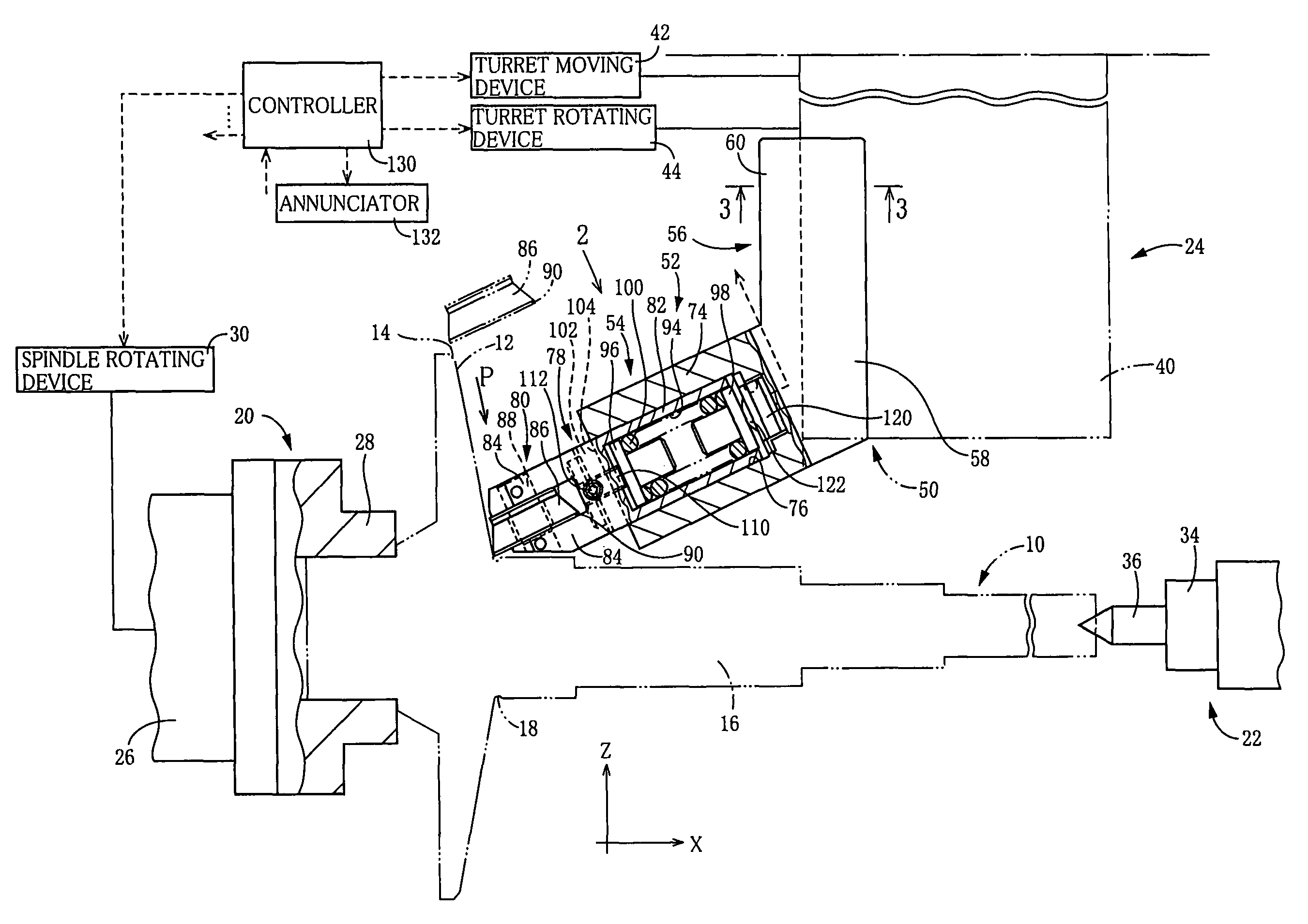
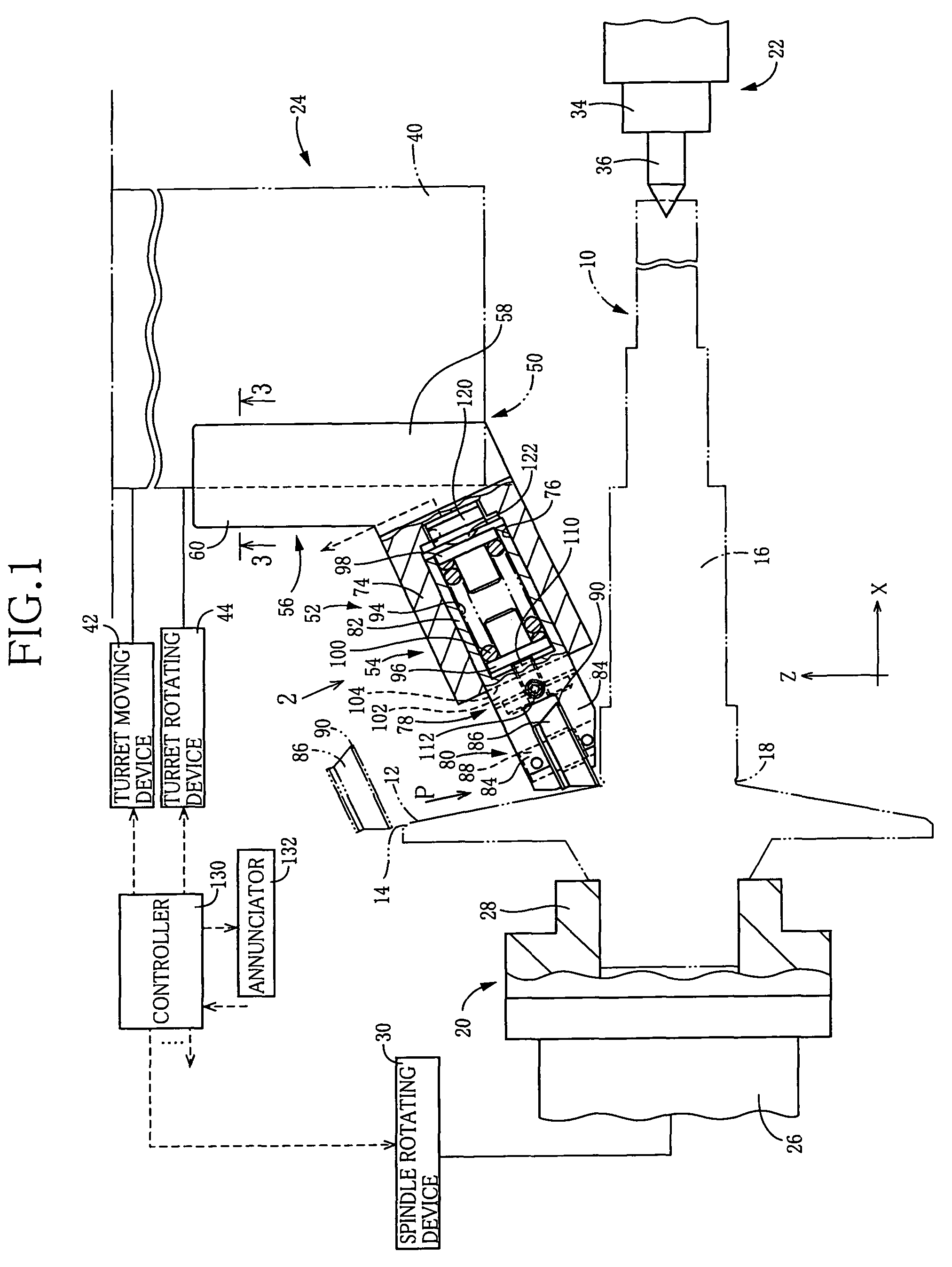
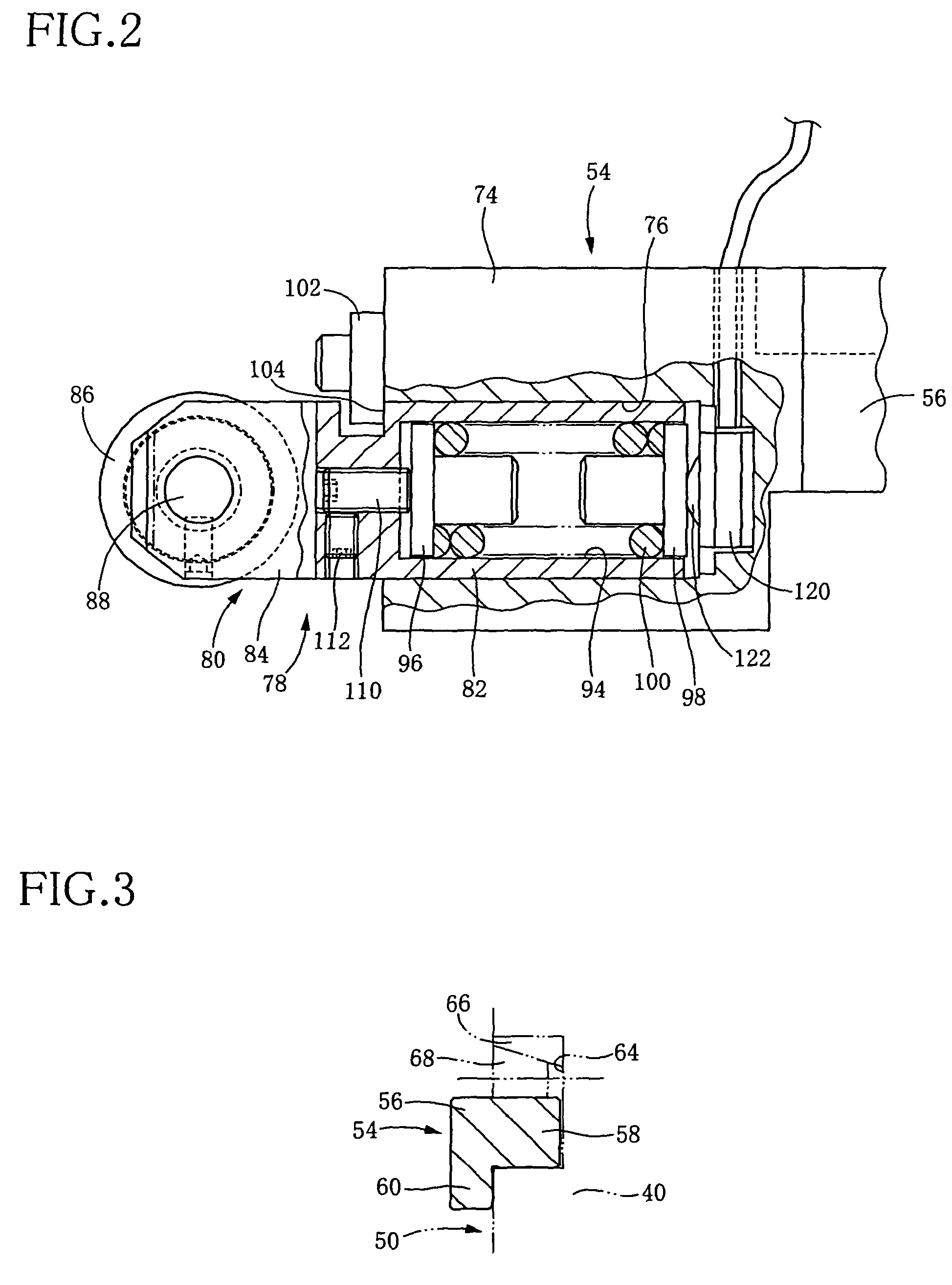
[0082]Referring to FIGS. 1-4, there will be described a roller burnishing apparatus with a pressing-force detecting device according to the claimable inventions, which takes the form of a turret lathe as a kind of processing machine and holding a roller burnishing tool device. The roller burnishing apparatus of the present embodiment implements a roller burnishing operation on an object surface, for instance which may be a sheave surface 12 of a pulley mounted on a shaft 16, which shaft-mounted pulley is for use in a CVT (Continuously Variable Transmission). The shaft-mounted pulley as a workpiece or an object to be burnished is shown in FIG. 1, and may be hereinafter simply referred to as “the pulley 10.” The sheave surface 12 is constituted by an outer circumferential surface of a circular truncated cone, whose center line coincides with an axis of the pulley 10. At a peripheral edge of the sheave surface 12, the pulley 10 is chamfered to provide the sheave surface 12 with a taper...

second embodiment

[0099]There will be described a roller burnishing apparatus with a pressing-force detecting device, according to the claimable inventions, with reference to FIGS. 5-7. An object surface that the roller burnishing apparatus burnishes is a straight cylindrical or circumferential outer surface 202 of an object 200 that is stepped and circular in cross section. That is, the object includes a small-diameter portion. At one of two axial ends of the object 200, the object 200 is chamfered to provide the cylindrical outer surface 202 with a guiding portion 204. At the other axial end of the object 200, a recess 206 is formed.

[0100]The present roller burnishing apparatus includes a roller burnishing tool device 210 held by a turret lathe. The roller burnishing tool device 210 has a tool mainbody 212 as a first member. At the tool mainbody 212, the roller burnishing tool device 210 is detachably held by a tool holding portion 50 of a turret 40. The tool mainbody 212 is block-shaped as shown i...

third embodiment

[0108]There will be described a roller burnishing apparatus with a pressing-force detecting device according to the claimable inventions, with reference to FIGS. 8 and 9.

[0109]Similar to the roller burnishing apparatus shown in FIGS. 5-7, the roller burnishing apparatus of the third embodiment performs burnishing on a straight cylindrical or circumferential outer surface 202 of an object 200, and includes a roller burnishing tool device 300 held by a turret lathe and including a tool mainbody 302 as a first member. The roller burnishing tool device 300 is positioned relative to a tool holding portion 50 of a turret 40 and detachably fixed thereon. A burnishing roller 304 is held by a swing arm 306 as a movable member constituting a second member, such that the burnishing roller 304 is rotatable. The burnishing roller 304 is similar in structure to the burnishing rollers 86, 230, and includes a burnishing portion308.

[0110]The tool mainbody 302 has an elongate shape. On a side surface...


PUM

PropertyMeasurementUnit
biasing forceaaaaaaaaaa
rotationaaaaaaaaaa
forceaaaaaaaaaa

Abstract

There is disclosed a roller burnishing apparatus including a first member moved relative to an object to be burnished, a second member movable relative to the first member in a relative movement direction, a burnishing roller held by the second member such that the burnishing roller is rotatable, a biasing device which biases with a biasing force the second member relative to the first member in one of two opposite directions along the relative movement direction, and a pressing-force detecting device that detects a pressing force with which the burnishing roller is pressed against the object and which is based on the biasing force of the biasing device.

Description

CROSS REFERENCE TO RELATED APPLICATION[0001]The present application is based on Japanese Patent Application No. 2007-137100, which was filed on May 23, 2007, the disclosure of which is herein incorporated by reference in its entirety.BACKGROUND OF THE INVENTION[0002]1. Field of the Invention[0003]The present invention relates to a roller burnishing apparatus, and particularly to an apparatus for burnishing an object by biasing and pressing a burnishing roller against the object.[0004]2. Description of Related Art[0005]As disclosed in JP-A-2000-52244, for instance, a burnishing roller is biased by a biasing force of a plurality of disc springs and pressed against a workpiece or an object to be burnished. That is, in a roller burnishing apparatus disclosed in the above-mentioned publication, a shaft portion of a roller holder is fitted in a fitting hole formed in a mainbody of a roller burnishing tool such that the shaft portion is axially movable relative to the mainbody, and the bur...

Claims


Application Information

Patent Timeline
Patent Type & Authority Patents(United States)
IPC IPC(8): B24B39/00
CPCB24B39/04B24B49/16Y10T29/474Y10T29/476Y10T29/477Y10T29/47
Inventor TOMIOKA, MITSUHIKOSEGAWA, TOSHIAKIMATSUBARA, MASAMI
Owner NISSAN MOTOR CO LTD
Why Eureka
Try Eureka