Sand Control Screen Assembly and Method for Use of Same

a technology of sand control screen and assembly, which is applied in the direction of sealing/packing, drilling pipes, and wellbore/well accessories, etc., can solve the problems of abrasive wear of components within the well, need for an expensive workover, and many problems

Inactive Publication Date: 2009-07-09
HALLIBURTON ENERGY SERVICES INC
View PDF99 Cites 63 Cited by
  • Summary
  • Abstract
  • Description
  • Claims
  • Application Information

AI Technical Summary

Benefits of technology

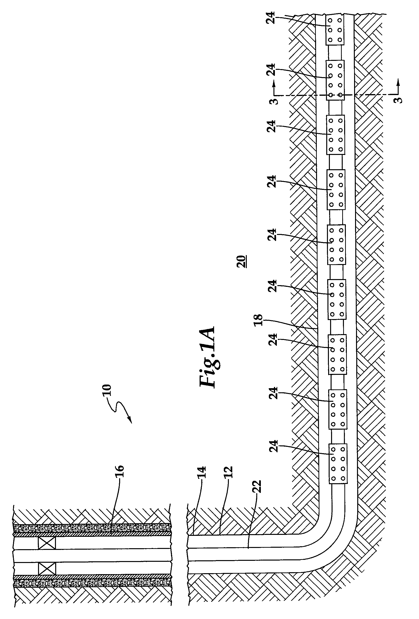
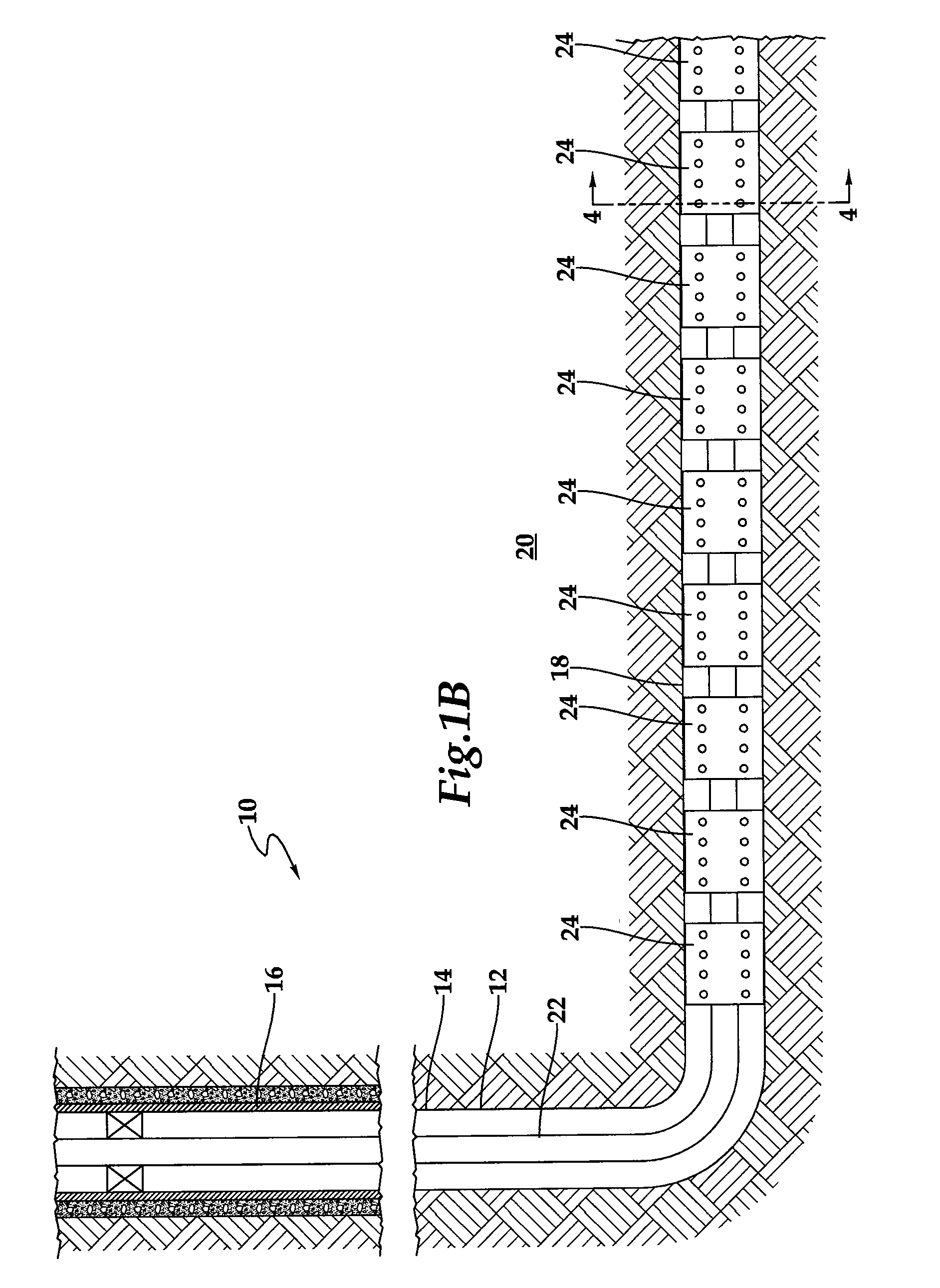
[0010]The present invention disclosed herein comprises a sand control screen assembly that prevents the production of particulate materials from a well that traverses a hydrocarbon bearing subterranean formation. The sand control screen assembly of the present invention achieves this result without the need for performing a gravel packing operation. In addition, the sand control screen assembly of the present invention provides radial support to the formation without the need for expanding metal tubulars and is suitable for operation in open hole completions and horizontal production intervals.
[0011]In one aspect, the present invention is directed to a sand control screen assembly including a base pipe having a plurality of openings that allow fluid flow therethrough and a swellable filter media disposed exteriorly of the base pipe and surrounding the plurality of openings. The swellable filter media is radially extendable between a first configuration and a second configuration in response to contact with an activating fluid. The swellable filter media is operable to allow fluid flow therethrough and prevent particulate flow of a predetermined size therethrough.
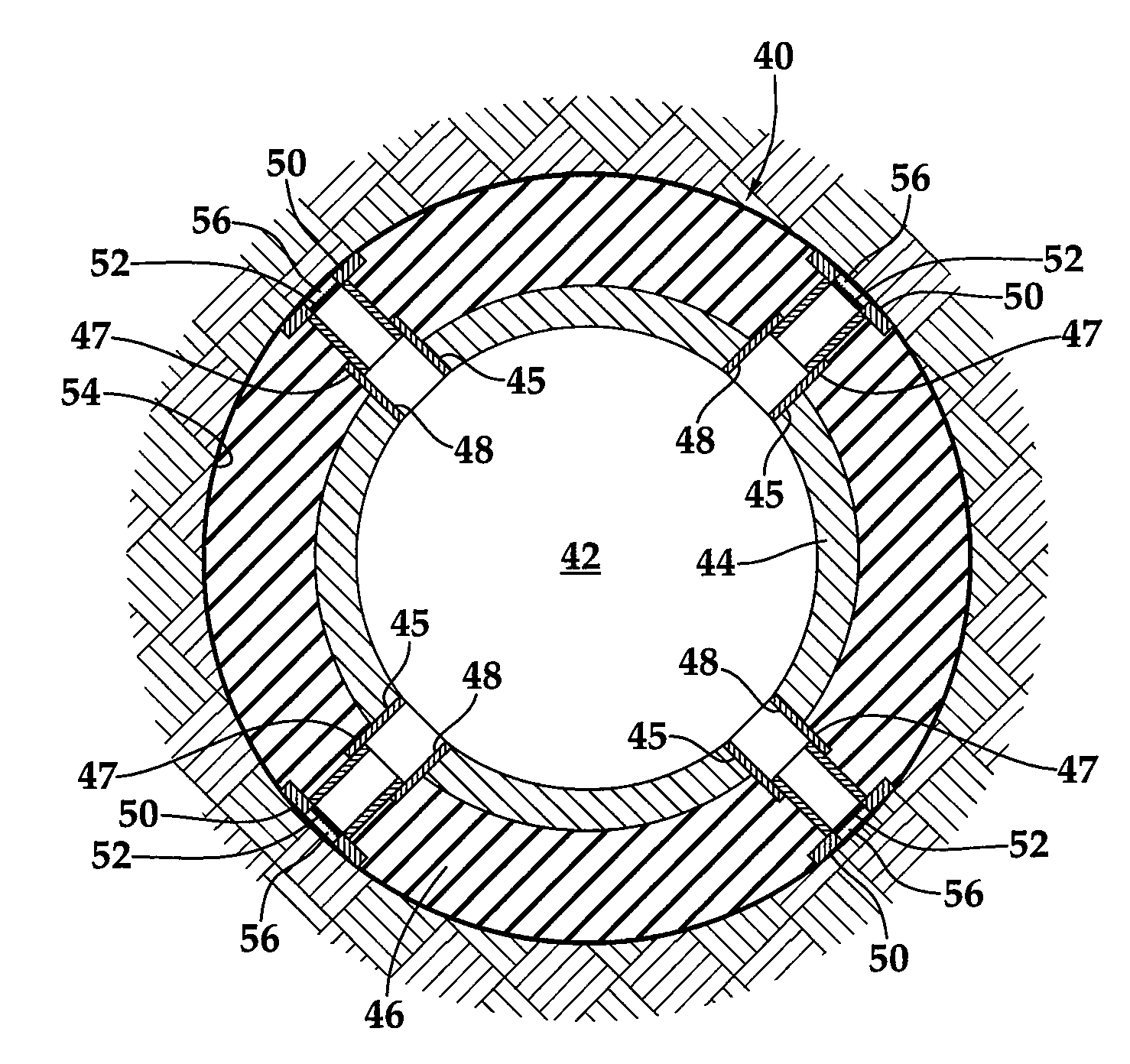
[0013]In another aspect, the present invention is directed to a sand control screen assembly that includes base pipe having at least one opening in a sidewall portion thereof and a swellable material layer disposed exteriorly of the base pipe and having at least one opening corresponding to the at least one opening of the base pipe. A telescoping perforation is operably associated with the at least one opening of the base pipe and is at least partially disposed within the at least one opening of the swellable material layer. A filter medium is disposed within the telescoping perforation. In operation, radial expansion of the swellable material layer, in response to contact with an activating fluid, causes the telescoping perforation to radially outwardly extend.
[0015]In a further aspect, the present invention is directed to a sand control screen assembly that includes a base pipe having a plurality of openings in a sidewall portion thereof and defining an internal flow path. A swellable material layer is disposed exteriorly of the base pipe and has a plurality of openings that correspond to the openings of the base pipe. A plurality of telescoping perforations is operably associated with the openings of the base pipe and at least partially disposed within the corresponding openings of the swellable material layer. The telescoping perforations provide fluid flow paths between a fluid source disposed exteriorly of the base pipe and the interior flow path. A filter medium is disposed within each of the telescoping perforations. In operation, radial expansion of the swellable material layer, in response to contact with an activating fluid, causes the telescoping perforation to radially outwardly extend.

Problems solved by technology

Numerous problems may occur as a result of the production of such particulate materials.
For example, the particulate materials cause abrasive wear to components within the well, such as tubing, pumps and valves.
In addition, the particulate materials may partially or fully clog the well creating the need for an expensive workover.
It has been found, however, that a complete gravel pack of the desired production interval is difficult to achieve particularly in long or inclined / horizontal production intervals.
These incomplete packs are commonly a result of the liquid carrier entering a permeable portion of the production interval causing the gravel to form a sand bridge in the annulus.
Thereafter, the sand bridge prevents the slurry from flowing to the remainder of the annulus which, in turn, prevents the placement of sufficient gravel in the remainder of the annulus.
It has been found, however, that conventional expandable sand control screens are not capable of contacting the wall of the wellbore along their entire length as the wellbore profile is not uniform.
More specifically, due to the process of drilling the wellbore and heterogeneity of the downhole strata, washouts or other irregularities commonly occur which result in certain locations within the wellbore having larger diameters than other areas or having non circular cross sections.
Thus, when the expandable sand control screens are expanded, voids are created between the expandable sand control screens and the irregular areas of the wellbore.
In addition, it has been found that the expansion process undesirably weakens such sand control screens.
It has been found, however, that in substantially horizontal production intervals, the telescoping screen members may not properly deploy, particularly along the portion of the production string resting on the bottom surface of the wellbore.
Failure to fully extend all the telescoping screen members results in a non uniform inner bore which may prevent the passage of tools therethrough.

Method used


Image

  • Sand Control Screen Assembly and Method for Use of Same
  • Sand Control Screen Assembly and Method for Use of Same
  • Sand Control Screen Assembly and Method for Use of Same

Examples


embodiment 320

[0065]In addition to the aforementioned aspects and embodiments of the present sand control screen assemblies, the present invention further includes methods for making a sand control screen assembly. FIG. 14 illustrates an embodiment 320 of an exemplary process for making a sand control screen assembly. In step 322, a base pipe is provided of a desired length for use in a desired application. In step 324, a coating of swellable material is disposed on the exterior of the base pipe. This step may include any type of application process appropriate for the swellable materials disclosed herein, including: dipping, spraying, wrapping, applying and the like. Generally, the swellable material is applied in a desired length on the base pipe according to the desired application in the wellbore. Also, the location of the swellable material on the base pipe may be determined by where the base pipe will be in the wellbore in relation to the production areas.

[0066]In step 326, openings are cre...

embodiment 340

[0068]FIG. 15 illustrates an embodiment 340 of an exemplary process for controlling sand and hydrocarbon production from a production interval. In step 342, a wellbore is drilled such that is traverses a subterranean hydrocarbon bearing formation. This step may include placing various casings or liners in the wellbore and performing various other well construction activities prior to insertion of the work string including one or more sand control screen assemblies of the present invention. In step 344, one or more sand control screen assemblies are inserted into the wellbore and the sand control screen assemblies are positioned adjacent to their respective production intervals. In this step, the sand control screen assemblies are preferably run into a hole with a smooth inner bore and smooth outer bore to minimize the risk of getting stuck.

[0069]In step 346, an activating fluid, such as a hydrocarbon, contacts the sand control screen assemblies and they expand, extend and / or swell r...


PUM


Abstract

A sand control screen assembly (40) includes a base pipe (44) having a plurality of openings (45) in a sidewall portion thereof and a swellable material layer (46) disposed exteriorly of the base pipe (44) and having a plurality of openings (47) that correspond to the openings (45) of the base pipe (44). A plurality of telescoping perforations (48) are operably associated with the openings (45) of the base pipe (44) and at least partially disposed within the corresponding openings (47) of the swellable material layer (46). A filter medium (56) is disposed within each of the telescoping perforations (48). In operation, radial expansion of the swellable material layer (46), in response to contact with an activating fluid, causes the telescoping perforations (48) to radially outwardly extend.

Description

TECHNICAL FIELD OF THE INVENTION[0001]This invention relates, in general, to controlling the production of particulate materials from a hydrocarbon formation and, in particular, to a sand control screen assembly having a swellable material layer that is operable to radially extend a plurality of telescoping perforations having particulate filtering capability into contact with the formation.BACKGROUND OF THE INVENTION[0002]Without limiting the scope of the present invention, its background is described with reference to the production of hydrocarbons through a wellbore traversing an unconsolidated or loosely consolidated formation, as an example.[0003]It is well known in the subterranean well drilling and completion art that particulate materials such as sand may be produced during the production of hydrocarbons from a well traversing an unconsolidated or loosely consolidated subterranean formation. Numerous problems may occur as a result of the production of such particulate materi...

Claims


Application Information

Patent Timeline
Patent Type & Authority Applications(United States)
IPC IPC(8): E03B3/18E21B33/12
CPCE21B43/086E21B43/082
Inventor DUSTERHOFT, RONALD GLENFERGUSON, CARL BISMARK
Owner HALLIBURTON ENERGY SERVICES INC
Why Eureka
Try Eureka