Plasma processing apparatus

a processing apparatus and plasma technology, applied in the direction of coatings, chemical vapor deposition coatings, electric discharge tubes, etc., can solve the problems of reducing the ease of maintenance for reducing the efficiency and reducing the ease of installation of the sample mounting electrode drive mechanism, so as to prevent the production of particles and prevent the influence of particles

Inactive Publication Date: 2006-10-26
HITACHI HIGH-TECH CORP
View PDF3 Cites 66 Cited by
  • Summary
  • Abstract
  • Description
  • Claims
  • Application Information

AI Technical Summary

Benefits of technology

[0013] In light of these problems, the invention provides a plasma processing apparatus capable of preventing the production of particle and preventing the influence of particle on the sample.
[0015] A plasma processing apparatus comprises a vacuum chamber; process gas introducing means for introducing process gas into the vacuum chamber; means, coupled to a first RF power supply, for applying RF energy to the process gas introduced into the vacuum chamber to turn the process gas into plasma; a sample mounting electrode for mounting a sample on an upper surface thereof and holding the sample in the vacuum chamber; evacuation means for evacuating the process gas in the vacuum chamber; and plasma confining means, provided on a peripheral side of the mounting electrode in the vacuum chamber, for inflecting flow of the process gas caused by the evacuation means on a downstream side of a sample mounting surface of the mounting electrode to prevent plasma from diffusing downstream of the sample mounting surface.
[0016] Because of the above configuration, the invention can provide a plasma processing apparatus capable of preventing the production of particle and preventing the influence of particle on the sample.

Problems solved by technology

For this reason, even if uniform plasma is generated, nonuniformity in the flow of process gas toward the sample will cause nonuniformity in the etching feature and in the rate distribution within the sample surface.
However, this method reduces ease of maintenance for the sample mounting electrode and makes it difficult to install a mechanism for driving a sample conveying means used for arbitrarily setting the processing position of the sample.
Moreover, in such an arrangement where gas is fed like a shower from a surface opposed to the sample and the evacuation port of a vacuum pump serving as a gas evacuating means is located directly below the sample mounting electrode, fine particles accumulated on the lower side face of the sample mounting electrode and on the vacuum chamber wall around the evacuation port are stirred up during plasma generation, which may be attached to the sample surface to cause particle contamination.
Since plasma is easy to diffuse around the evacuation port, the diffused plasma deteriorates the vacuum chamber wall, which is associated with particle contamination.
While particle production may be reduced by using yttria or other material with excellent plasma resistance for the vacuum chamber wall, coating the entire area with yttria would increase cost because such material is expensive.
Such particle is an obstacle to meeting the demands of device manufacture for an increasingly higher precision.

Method used


Image

  • Plasma processing apparatus
  • Plasma processing apparatus
  • Plasma processing apparatus

Examples


first embodiment

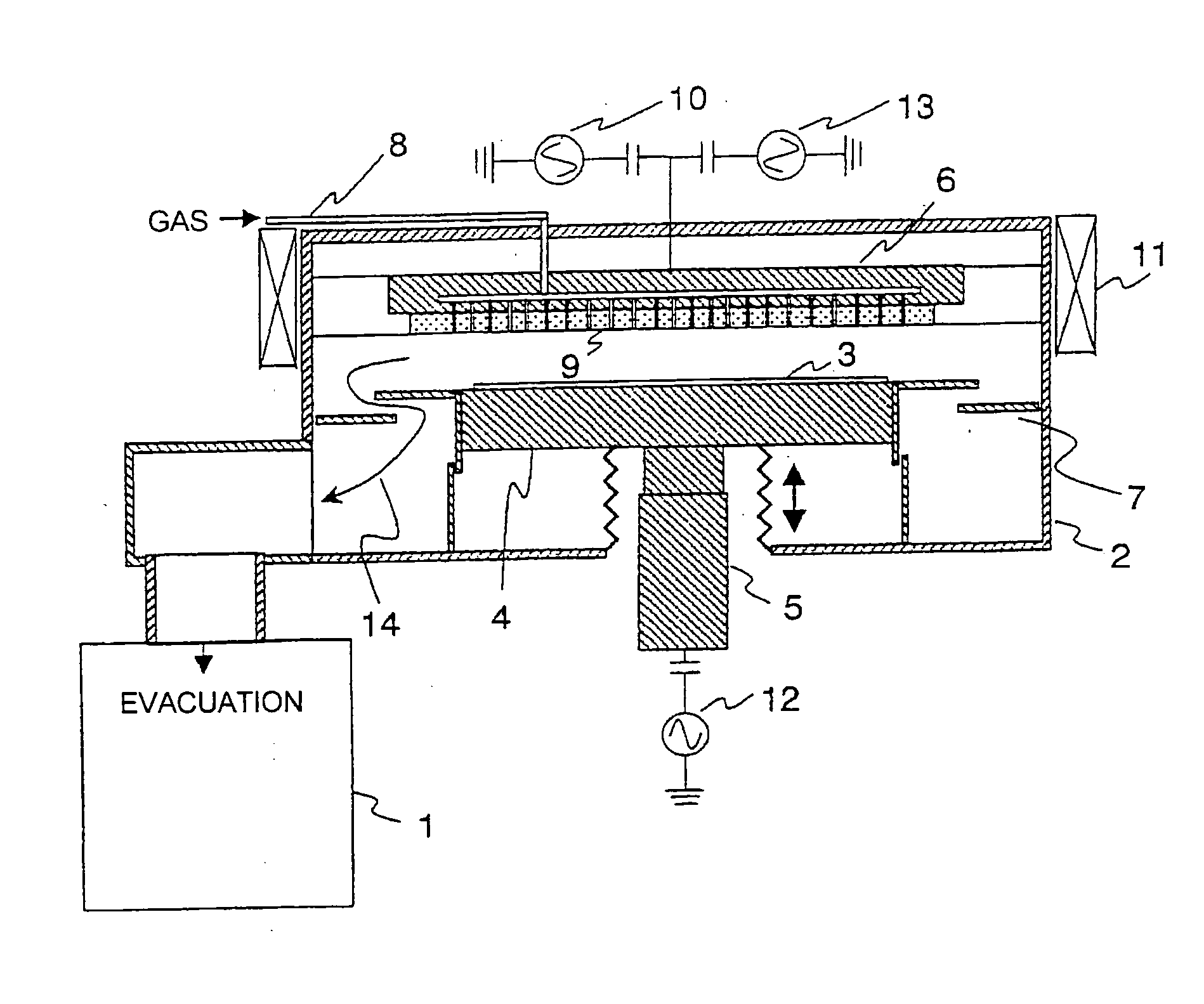
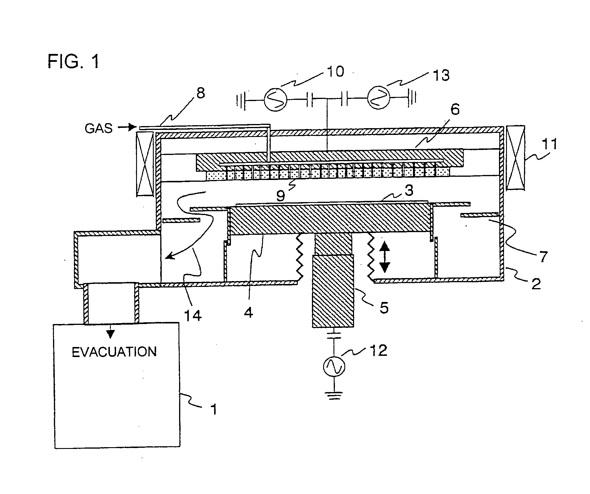
[0024] Preferred embodiments will now be described with reference to the accompanying drawings. FIG. 1 illustrates a plasma processing apparatus according to the invention. As shown in FIG. 1, the plasma processing apparatus comprises a vacuum chamber 2 evacuated by an evacuating means 1, a sample mounting electrode 4 for mounting a sample 3 in the vacuum chamber 2, and an upper electrode 6 located on a surface opposite to the sample 3.

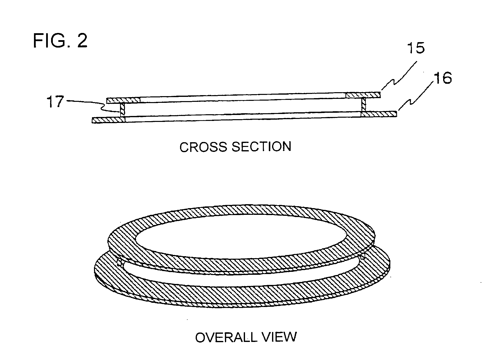
[0025] A plasma confining means 7 composed of two annular plates is placed between the sample mounting electrode 4 and the inner wall of the vacuum chamber 2. The sample mounting electrode 4 is also equipped with a vertical driving mechanism 5 capable of driving the mounting means vertically and adjusting the relative distance between the sample 3 and the upper electrode 6.

[0026] The upper electrode 6 is equipped with a shower plate 9 for spreading process gas fed from a process gas introducing means 8 and supplying it onto the surface of the sample ...

second embodiment

[0045]FIG. 4 illustrates a plasma processing apparatus according to the invention. FIG. 5 illustrates more specifically the plasma confining means 19 in FIG. 4. As shown in FIGS. 4 and 5, the plasma confining means 19 is formed from a single annular plate through which a plurality of pores 20 are formed.

[0046] The pores formed through the annular plate constituting the plasma confining means 19 are opened at a certain angle relative to the thickness direction as shown in FIG. 5. The obliquely opened pores can serve to inflect gas flow one or more times, which has an effect similar to that achieved in the first embodiment shown in FIG. 1. In addition, when the aspect ratio (pore depth / pore diameter) of the pore shown in FIG. 5 is 1.5 or more, plasma is effectively shielded and particle is prevented from passing therethrough from the lower part of the vacuum chamber. When the aspect ration is less than 1.5, plasma extinction in the pores is insufficient, which results in passing plasm...


PUM

PropertyMeasurementUnit
aspect ratioaaaaaaaaaa
frequencyaaaaaaaaaa
frequencyaaaaaaaaaa

Abstract

The invention provides a plasma processing apparatus capable of preventing the production of particle and preventing the influence of particle on the sample. The plasma processing apparatus comprises a vacuum chamber; process gas introducing means for introducing process gas into the vacuum chamber; means, coupled to a first RF power supply, for applying RF energy to the process gas introduced into the vacuum chamber to turn the process gas into plasma; a sample mounting electrode for mounting a sample on an upper surface thereof and holding the sample in the vacuum chamber; evacuation means for evacuating the process gas in the vacuum chamber; and plasma confining means, provided on a peripheral side of the mounting electrode in the vacuum chamber, for inflecting flow of the process gas caused by the evacuation means on a downstream side of a sample mounting surface of the mounting electrode to prevent plasma from diffusing downstream of the sample mounting surface.

Description

[0001] The present application is based on and claims priority of Japanese patent application No. 2005-125227 filed on Apr. 22, 2005, the entire contents of which are hereby incorporated by reference. BACKGROUND OF THE INVENTION [0002] 1. Field of the Invention [0003] This invention relates to a plasma processing apparatus, and more particularly to a plasma processing apparatus capable of preventing the influence of particle. [0004] 2. Description of the Related Art [0005] In a dry etching apparatus, process gas is introduced into a vacuum chamber equipped with an evacuating means. The introduced process gas is turned into plasma by electromagnetic waves. A sample (e.g., a workpiece such as a wafer) is exposed to the plasma to etch its surface except its masked portion, and thus a desired feature is obtained. [0006] An RF voltage, different from the plasma generating voltage, is applied to the sample. The RF voltage accelerates ions in the plasma and causes them to impinge on the sa...

Claims


Application Information

Patent Timeline
Patent Type & Authority Applications(United States)
IPC IPC(8): C23F1/00C23C16/00
CPCH01J37/321H01L21/67069H01J37/32633H01J37/32623
Inventor YOKOGAWA, KENETSUMAEDA, KENJIKOBAYASHI, HIROYUKIIZAWA, MASARUKANEKIYO, TADAMITSU
Owner HITACHI HIGH-TECH CORP
Why Eureka
Try Eureka