Light-emitting-diode lamp

a technology of led lamps and led bulbs, which is applied in the direction of identification means, coupling device connections, lighting support devices, etc., can solve the problems of not meeting the requirements of energy saving, consuming high amount of electric energy of traditional electric bulbs, and generating high amount of heat, so as to reduce the heat produced by led lamps during the operation of them, the effect of reducing the cost and being easy to assembl

Inactive Publication Date: 2009-09-08
UWIN TECH
View PDF4 Cites 66 Cited by
  • Summary
  • Abstract
  • Description
  • Claims
  • Application Information

AI Technical Summary

Benefits of technology

[0003]A primary object of the present invention is to provide an LED lamp that can be easily assembled and is adjustable in the number of LEDs thereof according to desired illuminance, so that the LED lamp can be produced at lowered cost and the heat produced by the LED lamp during the operation thereof can be reduced.
[0007]It is possible to use a plurality of low-power LEDs instead of one single high-power LED to increase the illuminance while avoiding the production of high amount of heat. Therefore, the problem of heat dissipation in LED lamp may be solved.

Problems solved by technology

The traditional electric bulbs consume high amount of electric energy and no longer meet nowadays requirement for energy saving.
While the currently available LED lamps have high power to increase illumination thereof, they also produce high amount of heat during the operation thereof, and the produced heat is not easily dissipated.
Moreover, the currently available LED lamps are not easy to assemble, and are not adjustable in the number of LEDs thereof for providing desired illuminance (lumen).
Due to these factors, the current LED lamps always require high production cost.

Method used


Image

  • Light-emitting-diode lamp
  • Light-emitting-diode lamp
  • Light-emitting-diode lamp

Examples


Embodiment Construction

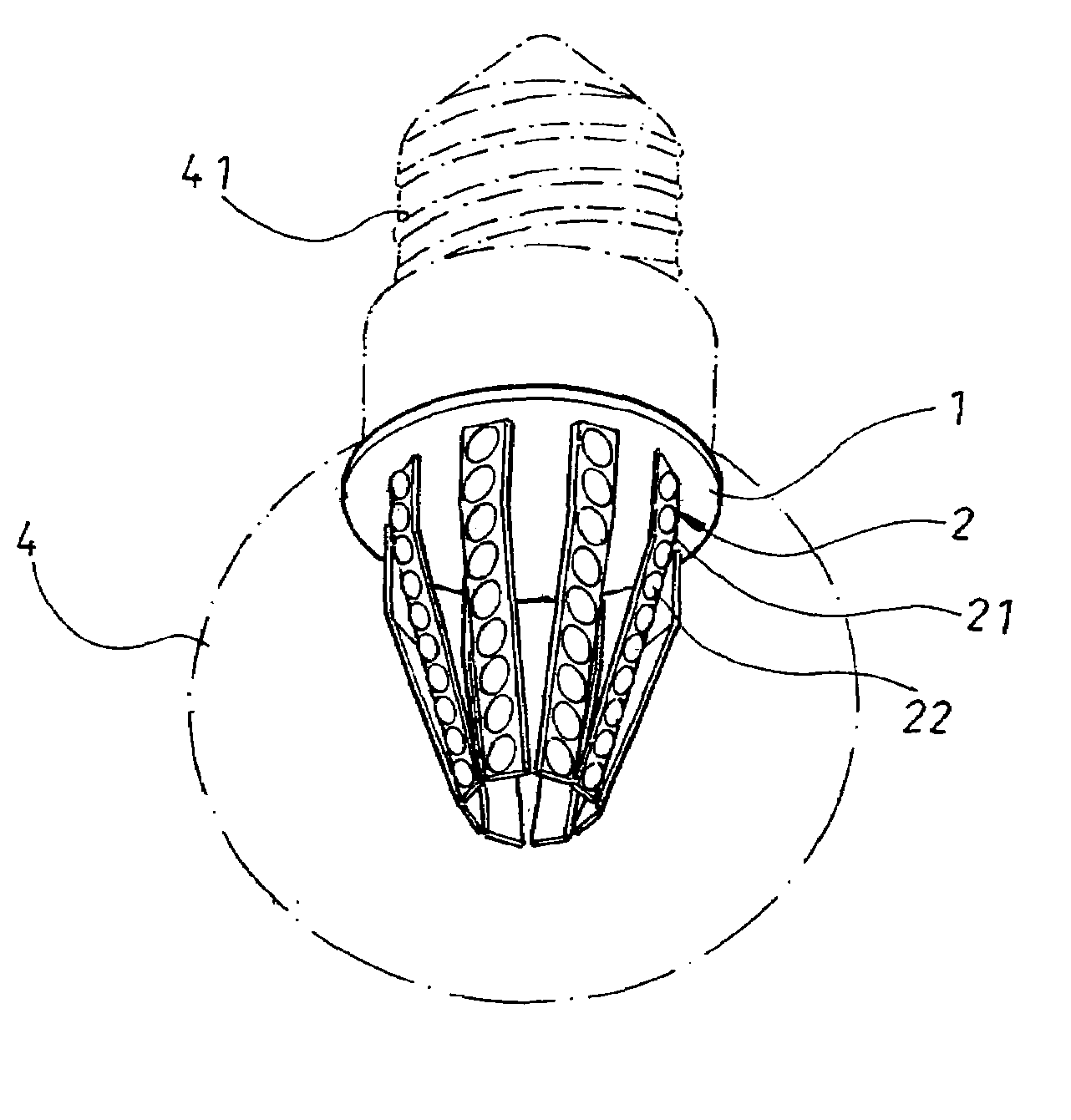
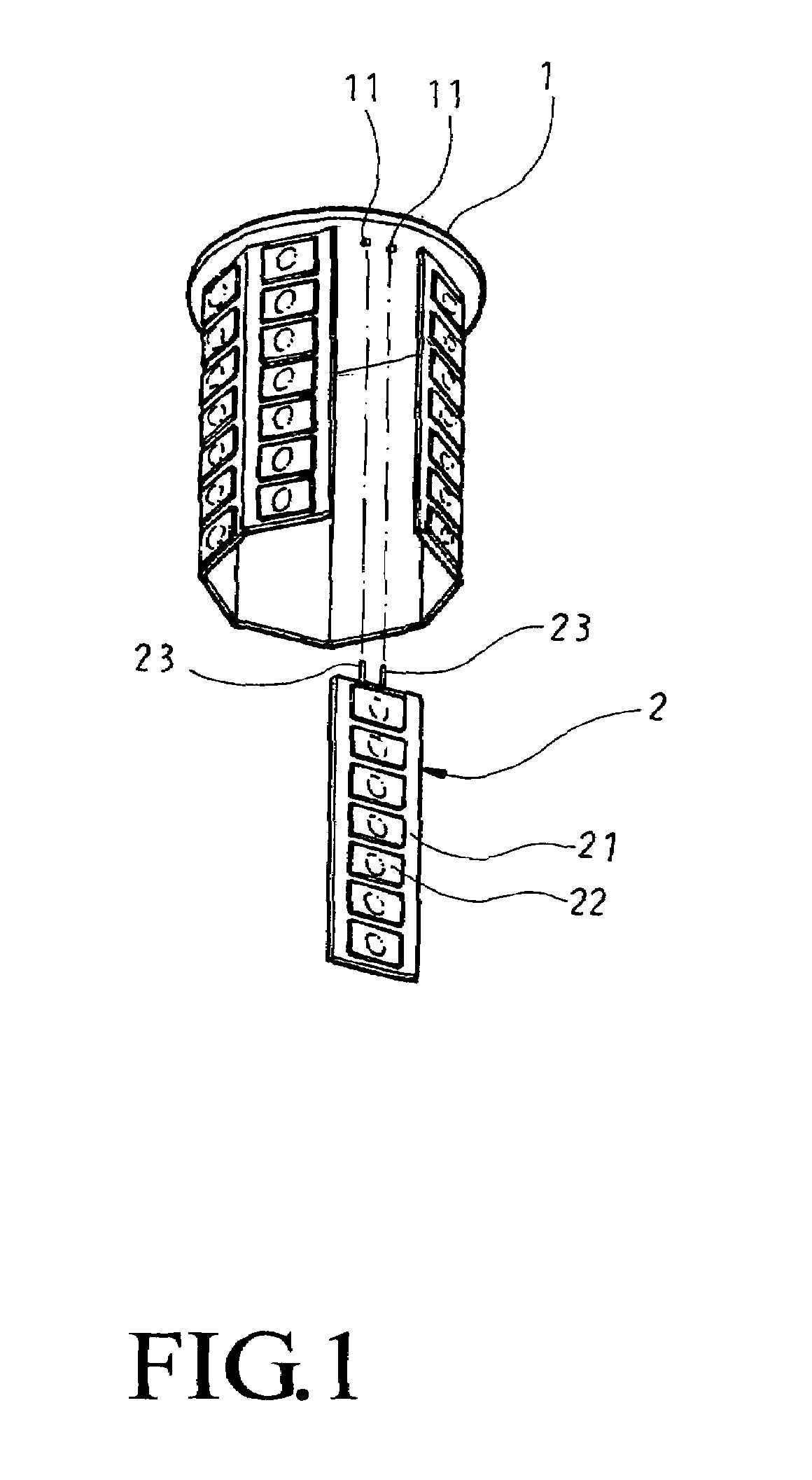
[0015]Please refer to FIG. 1 that is a partially exploded perspective view showing a control circuit board 1 and a plurality of LED units 2 for forming a light-emitting-diode (LED) lamp according to a first embodiment of the present invention.

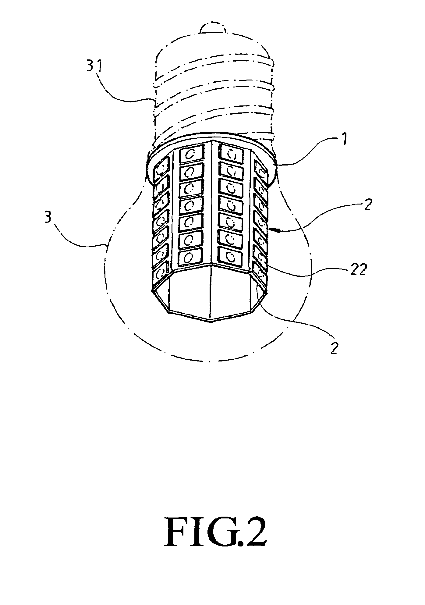
[0016]The control circuit board 1 is provided thereon a control circuit and a plurality of insertion holes 11 electrically connected to the control circuit. In the illustrated embodiment of the present invention, the control circuit board 1 is in the form of a disk, and the insertion holes 11 are octagonally arranged on the control circuit board 1.

[0017]Each of the LED units 2 includes a circuit board 21, a plurality of LEDs 22 mounted on the circuit board 21, and a plurality of terminals 23 provided on and projected from an end surface of the circuit board 21.

[0018]The LED units 2 are assembled to the control circuit board 1 and electrically connected to the control circuit by plugging the terminals 23 on the circuit boards 21 into the inserti...


PUM


Abstract

A light-emitting-diode (LED) lamp includes a control circuit board having a control circuit and a plurality of insertion holes provided thereon; a plurality of LED units, each of which including a circuit board, a plurality of LEDs mounted on the circuit board, and terminals provided at an end of the circuit board for plugging into the insertion holes on the control circuit board to thereby electrically assemble the LED unit to the control circuit board; and a glass bulb or tube for receiving the assembled control circuit board and LED units to complete the LED lamp that can be mounted to a general lamp holder. When electricity is supplied to the LED lamp, the LEDs are driven by the control circuit to emit light for illumination. The number of LED units and of the LEDs may be adjusted according to desired illuminance.

Description

FIELD OF THE INVENTION[0001]The present invention relates to a light-emitting-diode (LED) lamp, and more particularly to an LED lamp that can be easily assembled and is adjustable in the number of LEDs thereof according to desired illuminance.BACKGROUND OF THE INVENTION[0002]The traditional electric bulbs consume high amount of electric energy and no longer meet nowadays requirement for energy saving. The illumination technology employing light-emitting diodes (LED) has been developed to replace the traditional electric bulbs with LED lamps for the purpose of energy saving. While the currently available LED lamps have high power to increase illumination thereof, they also produce high amount of heat during the operation thereof, and the produced heat is not easily dissipated. Moreover, the currently available LED lamps are not easy to assemble, and are not adjustable in the number of LEDs thereof for providing desired illuminance (lumen). Due to these factors, the current LED lamps ...

Claims


Application Information

Patent Timeline
Patent Type & Authority Patents(United States)
IPC IPC(8): F21S4/00
CPCF21K9/135F21K9/17F21V3/0418H05B33/0803F21Y2101/02F21Y2111/007F21Y2103/003F21Y2111/005F21K9/232F21K9/27F21Y2103/10F21Y2115/10F21Y2107/30F21Y2107/40F21V3/061H05B45/34H05B45/3578
Inventor WU, TSU YAO
Owner UWIN TECH
Why Eureka
Try Eureka