
Pivoting footwear systems and configurable traction system

a technology of pivoting footwear and configurable traction system, which is applied in the direction of ski bindings, fastenings, skiing, etc., can solve the problems of increasing weight and hassle of packing up the necessary gear, excessive operation and high cost of prior approach ski snowboard systems, and heavy approach skis

Inactive Publication Date: 2009-07-16
EKBERG LANE
View PDF71 Cites 8 Cited by
  • Summary
  • Abstract
  • Description
  • Claims
  • Application Information

AI Technical Summary

Benefits of technology

[0011]The present invention is in response to the current state of the art, and in particular, in response to the problems and needs in the art that have not been fully solved by current available ski, snowboard, snowshoe, their foot binding devices, and needed footwear. Accordingly, the present invention has

Problems solved by technology

Unfortunately for such adventures, enthusiasts must pack extra equipment or heavy equipment for traversing winter terrain.
The added weight and hassle of packing up the necessary gear is an obvious disadvantage of these activities of hiking up an incline to then ski or snowboard down an incline.
Prior approach ski snowboard systems have been extremely heavy to operate and are expensive.
Approach skis are heavy and most do not accept snowboard boots.
They do not pack very easily, and they do not offer multi-functions wherein the user may quick release and attach a variety of foot binding set-ups.
The problem with this system includes: weight, expense, does not ski well down hill, and the snowboard does not ride as comfortably as a normal snowboard setup.
The approach ski mode is too heavy and limits the range a user can hike because of fatigue.
Snowshoes are too bulky and do not pack well.
This method is more tiring and time consuming.
The second solution is using a split-board which is very heavy, and it is very expensive.
The third solution is to use current approach free heel designs that are too heavy and expensive and do not pack well.

Method used


Image

  • Pivoting footwear systems and configurable traction system
  • Pivoting footwear systems and configurable traction system
  • Pivoting footwear systems and configurable traction system

Examples


Embodiment Construction

[0050]Reference throughout this specification to “one embodiment,”“an embodiment,” or similar language means that a particular feature, structure, or characteristic described in connection with the embodiment is included in at least one embodiment of the present invention. Thus, appearances of the phrases “in one embodiment,”“in an embodiment,” and similar language throughout this specification may, but do not necessarily, all refer to the same embodiment.

[0051]Furthermore, the described features, structures, or characteristics of the invention may be combined in any suitable manner in one or more embodiments. In the following description, numerous specific details are provided in order to give a thorough understanding of embodiments of the invention. One skilled in the relevant art will recognize, however, that the invention may be practiced without one or more of the specific details, or with other methods, components, materials, and so forth. In other instances, well-known struct...


PUM


Abstract

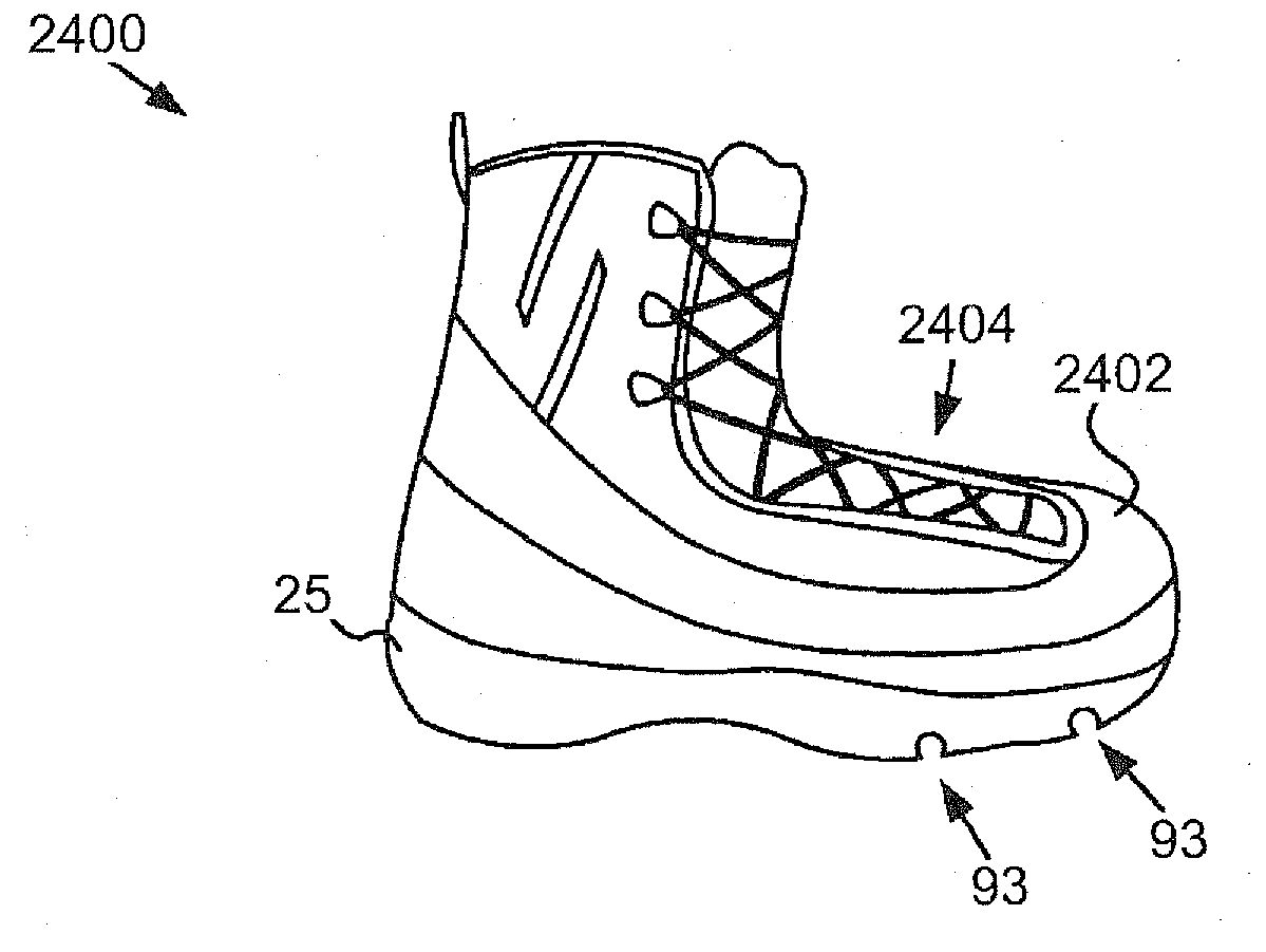
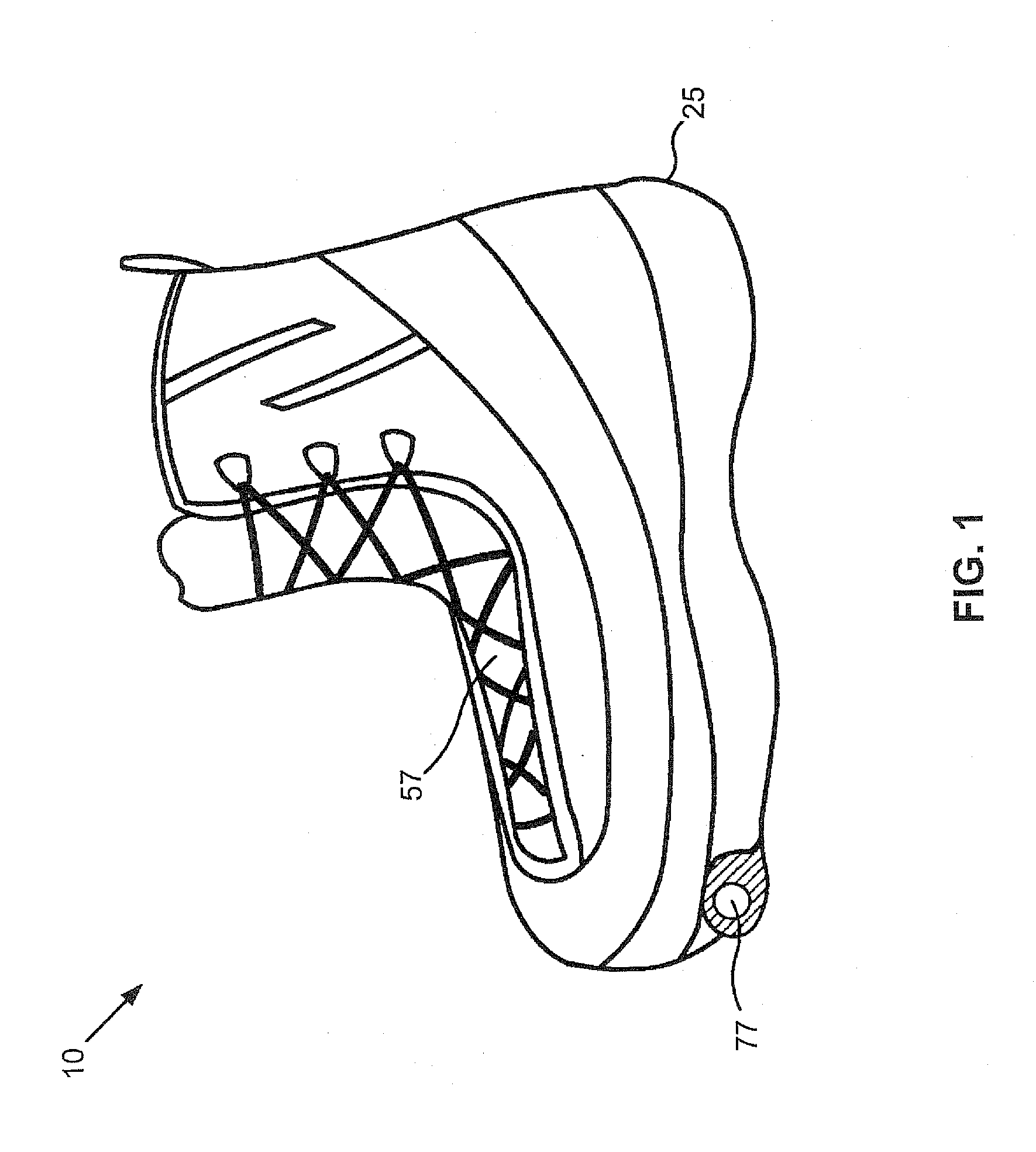
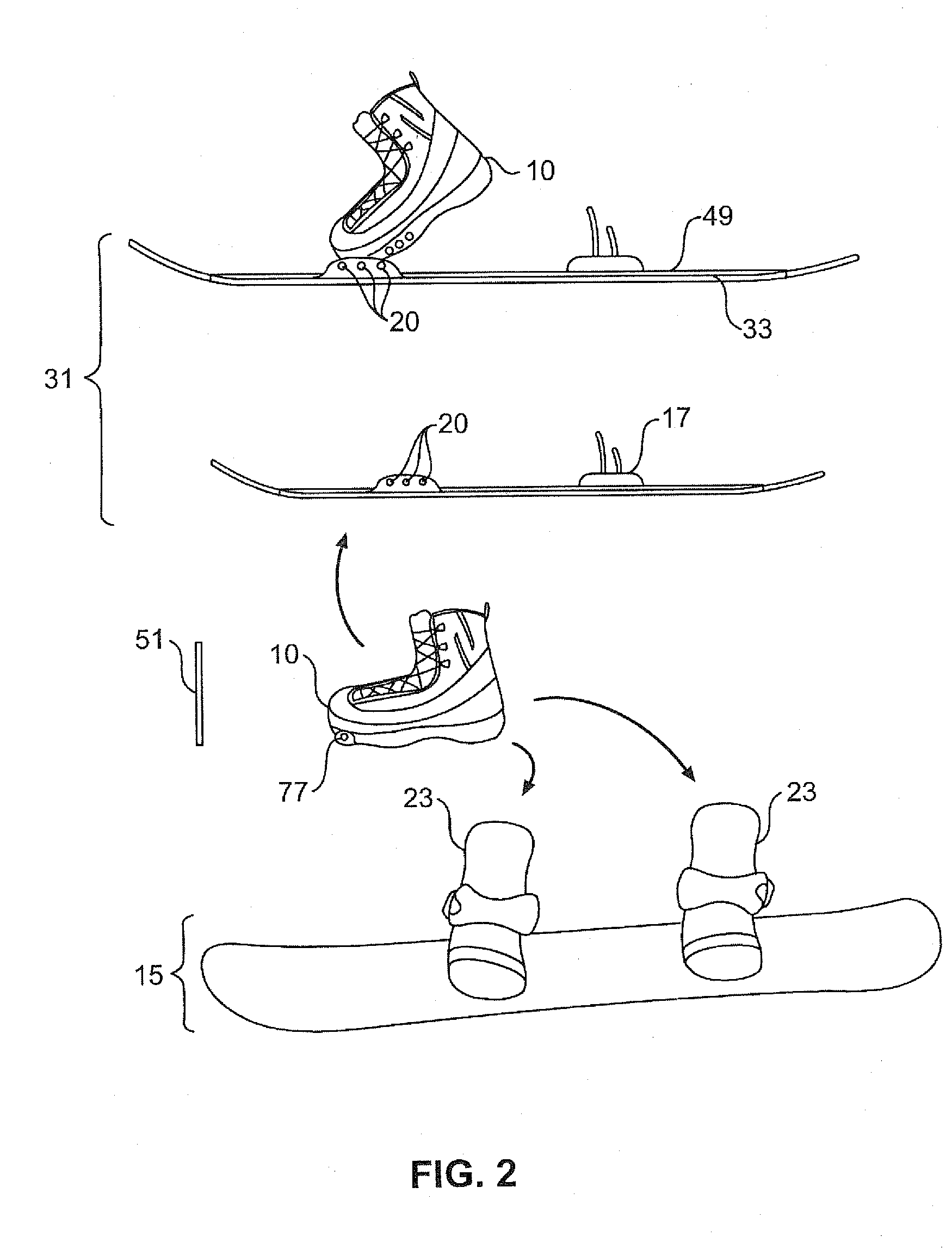
A device is disclosed that traverses terrain. The device includes a removable axle where the device is configured to traverse terrain, a groove connected with a boot for receiving the axle, the groove is configured to enable the boot to pivot about the axle and securely couple the boot with the axle. The groove may be formed in a boot and configured to receive the axle, or the groove may be formed in a mounting plate removably attachable with the boot and configured to receive the axle.

Description

CROSS-REFERENCES TO RELATED APPLICATIONS[0001]This application claims the priority benefit of Patent application No. PCT / US2007 / 067715 entitled “PIVOTING FOOTWEAR SYSTEMS AND, CONFIGURABLE TRACTION SYSTEMS” and U.S. Provisional Patent application No. 60 / 796,028 entitled “CONFIGURABLE CLIMBING SKI AND MOUNTING PLATE SYSTEM” and filed on Apr. 28, 2006, for Lane A. Ekberg which are incorporated herein by reference.BACKGROUND OF THE INVENTION[0002]1. Field of the Invention[0003]This invention relates to winter sports equipment and more particularly relates to a winter footwear pivot system allowing transition from one binding apparatus to another providing different modes of winter foot travel with a footwear pivot system. Also disclosed is a configurable crampon and a strapless crampon system as well as configurable traction.[0004]2. Description of the Related Art[0005]Approach “randonee” climbing skiing is a popular winter sport that provides backcountry exploration, exercise, and ent...

Claims


Application Information

Patent Timeline
IPC IPC(8): A63C9/08
CPCA43B5/0403A43B5/0417A43C15/068A63C5/02A63C7/005A63C2203/06A63C7/12A63C9/006A63C9/086A63C13/00A63C13/008A63C7/08
Inventor EKBERG, LANE
Owner EKBERG LANE
Learn More