Touch sensitive display with ultrasonic vibrations for tactile feedback

a tactile feedback and ultrasonic technology, applied in the field of input devices, can solve the problem of not having adequate solutions for providing tactile feedback to keypads

Inactive Publication Date: 2009-07-16
SONY ERICSSON MOBILE COMM AB
View PDF3 Cites 104 Cited by
  • Summary
  • Abstract
  • Description
  • Claims
  • Application Information

AI Technical Summary

Problems solved by technology

Currently, there are no adequate solutions of providing tactile feedback to keypads formed of a single physical device or surface, such as a touch sensitive surface.

Method used


Image

  • Touch sensitive display with ultrasonic vibrations for tactile feedback
  • Touch sensitive display with ultrasonic vibrations for tactile feedback
  • Touch sensitive display with ultrasonic vibrations for tactile feedback

Examples


Embodiment Construction

[0029]The following detailed description of the invention refers to the accompanying drawings. The same reference numbers in different drawings may identify the same or similar elements. Also, the following detailed description does not limit the embodiments.

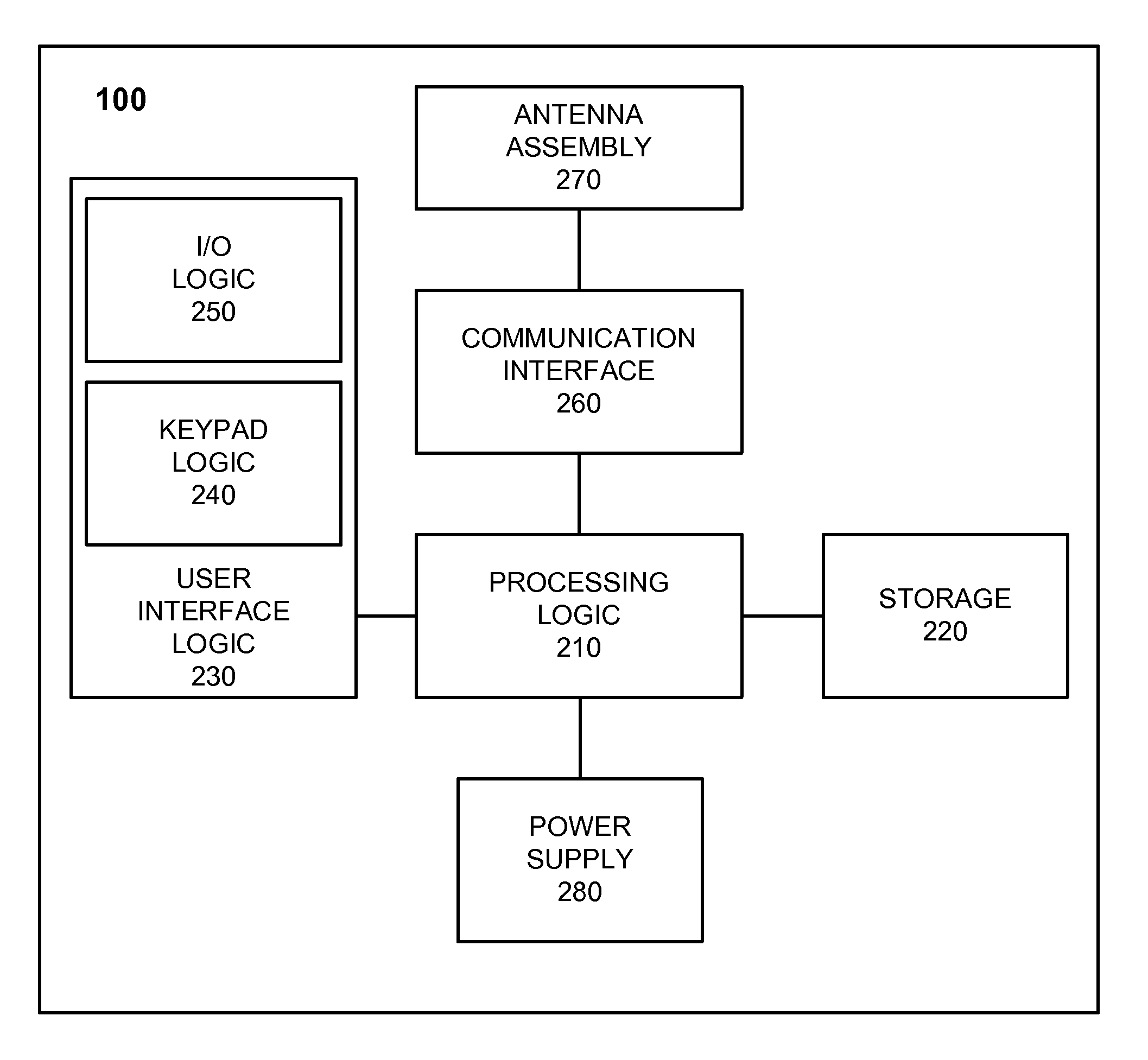
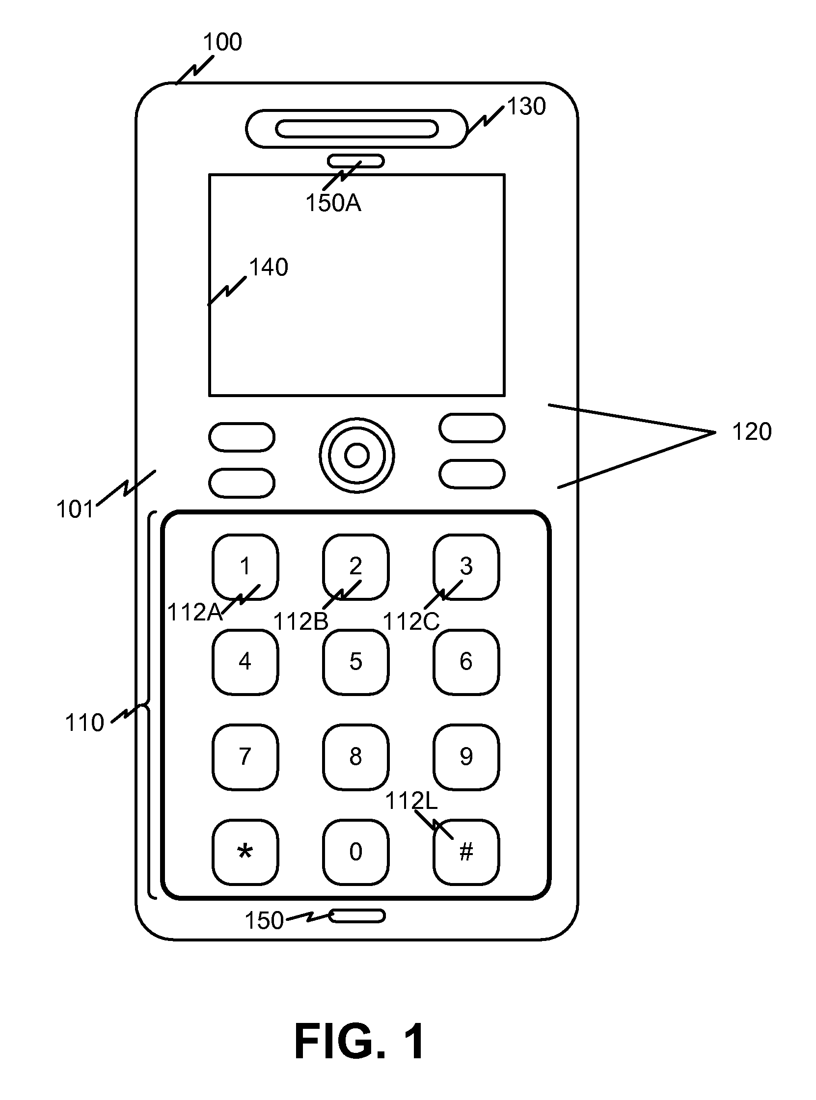
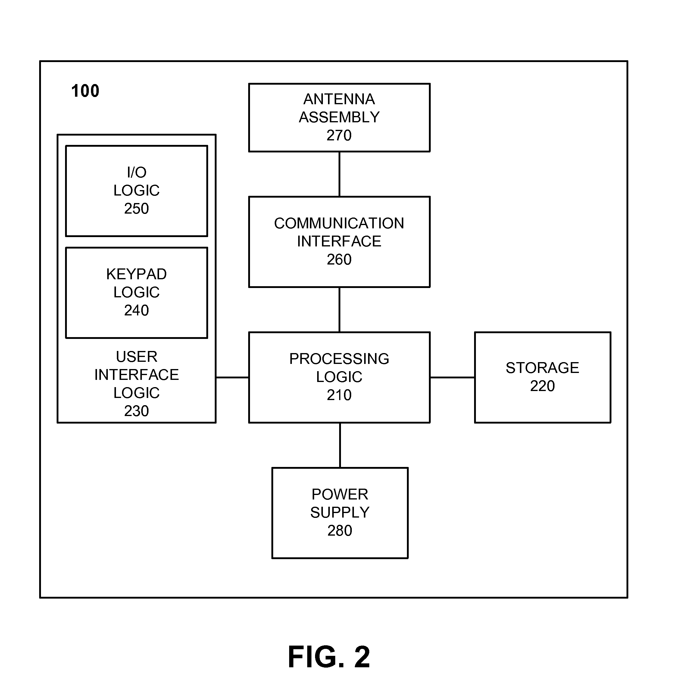
[0030]Exemplary implementations of the embodiments will be described in the context of a mobile communication terminal. It should be understood that a mobile communication terminal is an example of a device that can employ a keypad consistent with the principles of the embodiments and should not be construed as limiting the types or sizes of devices or applications that can use implementations of keypads described herein. For example, keypads consistent with the principles of the embodiments may be used on desktop communication devices, household appliances, such as microwave ovens and / or appliance remote controls, automobile radio faceplates, televisions, computer screens, industrial devices, such as testing equipment, etc.

[003...


PUM


Abstract

A mobile communication device may include logic configured to receive input on a touch sensitive surface of a device and activate an ultrasonic element to vibrate in response to the received input, where the vibration provides tactile feedback to a user indicating that the device has received the input.

Description

BACKGROUND OF THE INVENTION[0001]Implementations described herein relate generally to input devices, and more particularly, to handheld input devices that may provide tactile feedback in response to key entries.[0002]Devices, such as handheld mobile communication devices, conventionally include input devices that provide some form of tactile feedback to a user indicating that a keystroke has been detected by the communication device. These conventional keypads are formed of physically distinct keys. Currently, there are no adequate solutions of providing tactile feedback to keypads formed of a single physical device or surface, such as a touch sensitive surface.SUMMARY OF THE INVENTION[0003]According to one aspect, a mobile communication device is provided. The mobile communication device may comprise a keypad assembly comprising a touch sensitive cover, an ultrasonic element and a display for displaying characters, and logic configured to sense an input on the touch sensitive cover...

Claims


Application Information

Patent Timeline
Patent Type & Authority Applications(United States)
IPC IPC(8): H04M1/02
CPCG06F3/016G06F3/04886H01H2003/0293H04M2250/22H01H2231/022H04M1/23H04M1/72519H01H2215/052H04M1/724
Inventor PETTERSSON, HELENA ELISABET
Owner SONY ERICSSON MOBILE COMM AB
Why Eureka
Try Eureka