Automatic flooding protection for underground ventilation ducts

a technology of automatic flooding protection and underground ventilation ducts, which is applied in the direction of mining structures, construction, marine site engineering, etc., can solve the problems of inability to address the problem, not only expensive to implement for each sidewalk grating area, but also largely impractical

Active Publication Date: 2009-07-23
FLOODBREAK
View PDF8 Cites 38 Cited by
  • Summary
  • Abstract
  • Description
  • Claims
  • Application Information

AI Technical Summary

Problems solved by technology

These inventions do not address the problem of surface storm waters entering and flooding underground tunnels and chambers through ventilation ducts connecting the underground chambers or tunnels to air at ground surface.
In the case of subway systems, solutions have been suggested for reducing entrance of runoff water from street level grate openings t

Method used


Image

  • Automatic flooding protection for underground ventilation ducts
  • Automatic flooding protection for underground ventilation ducts
  • Automatic flooding protection for underground ventilation ducts

Examples


Embodiment Construction

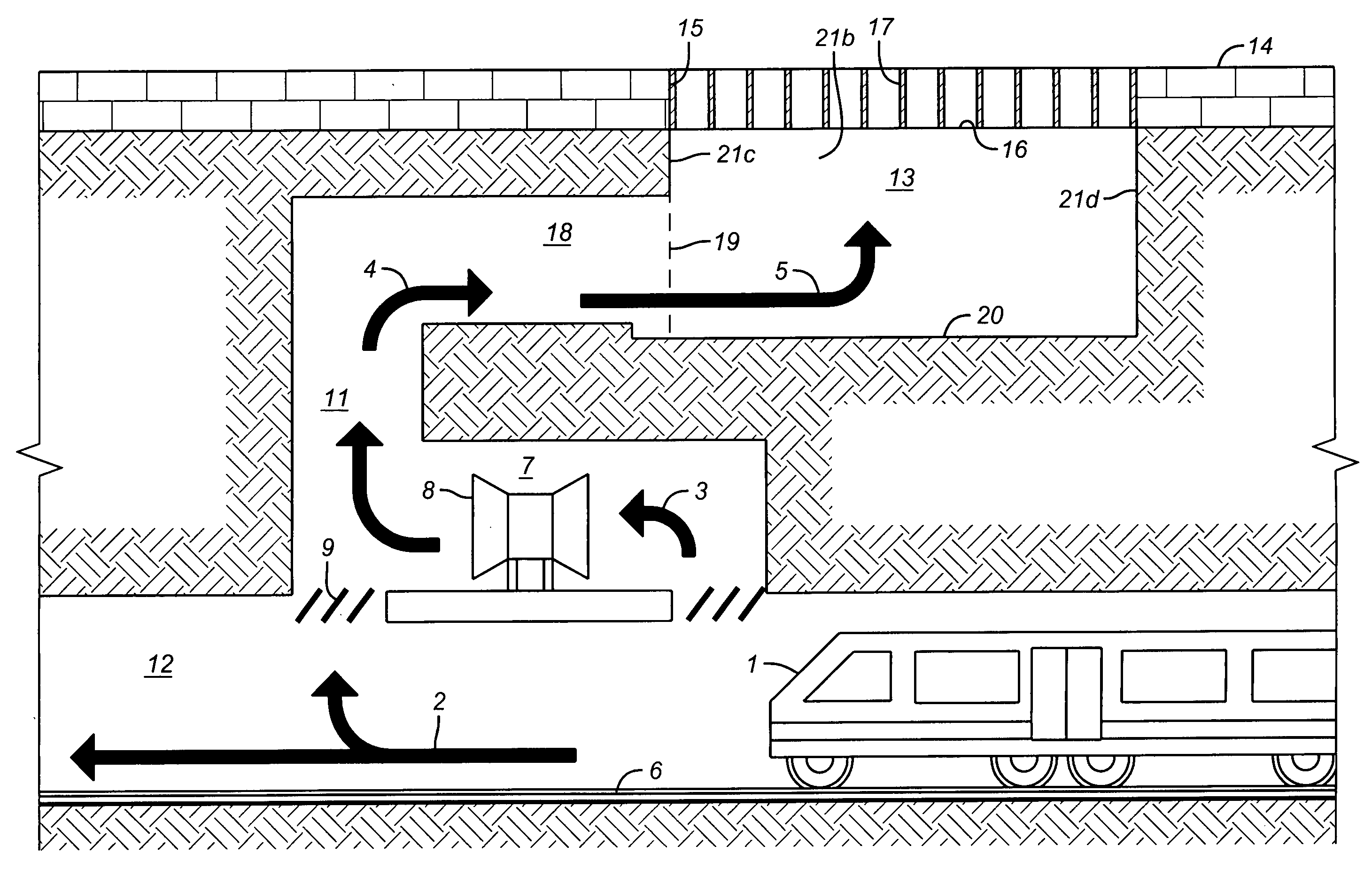
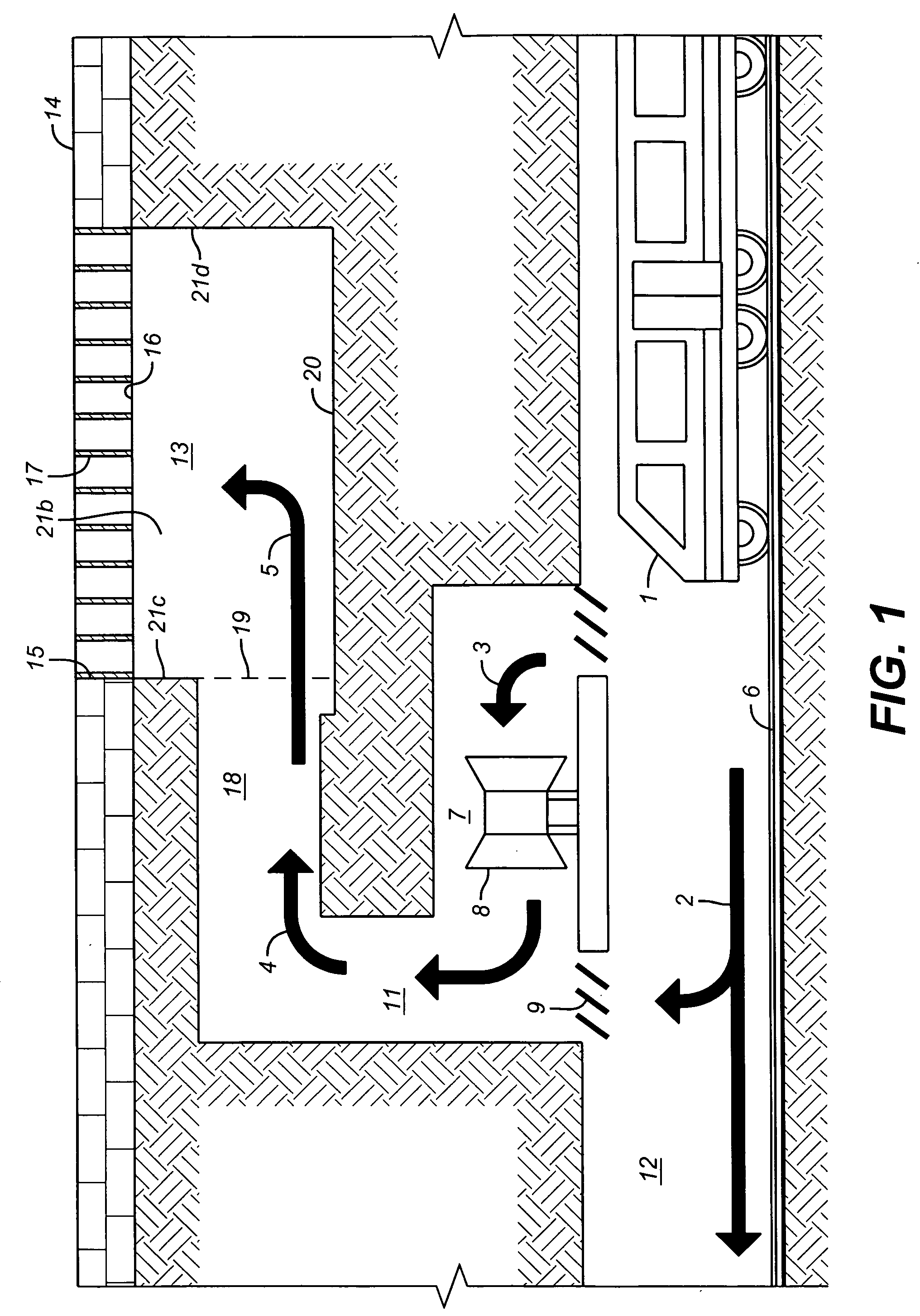
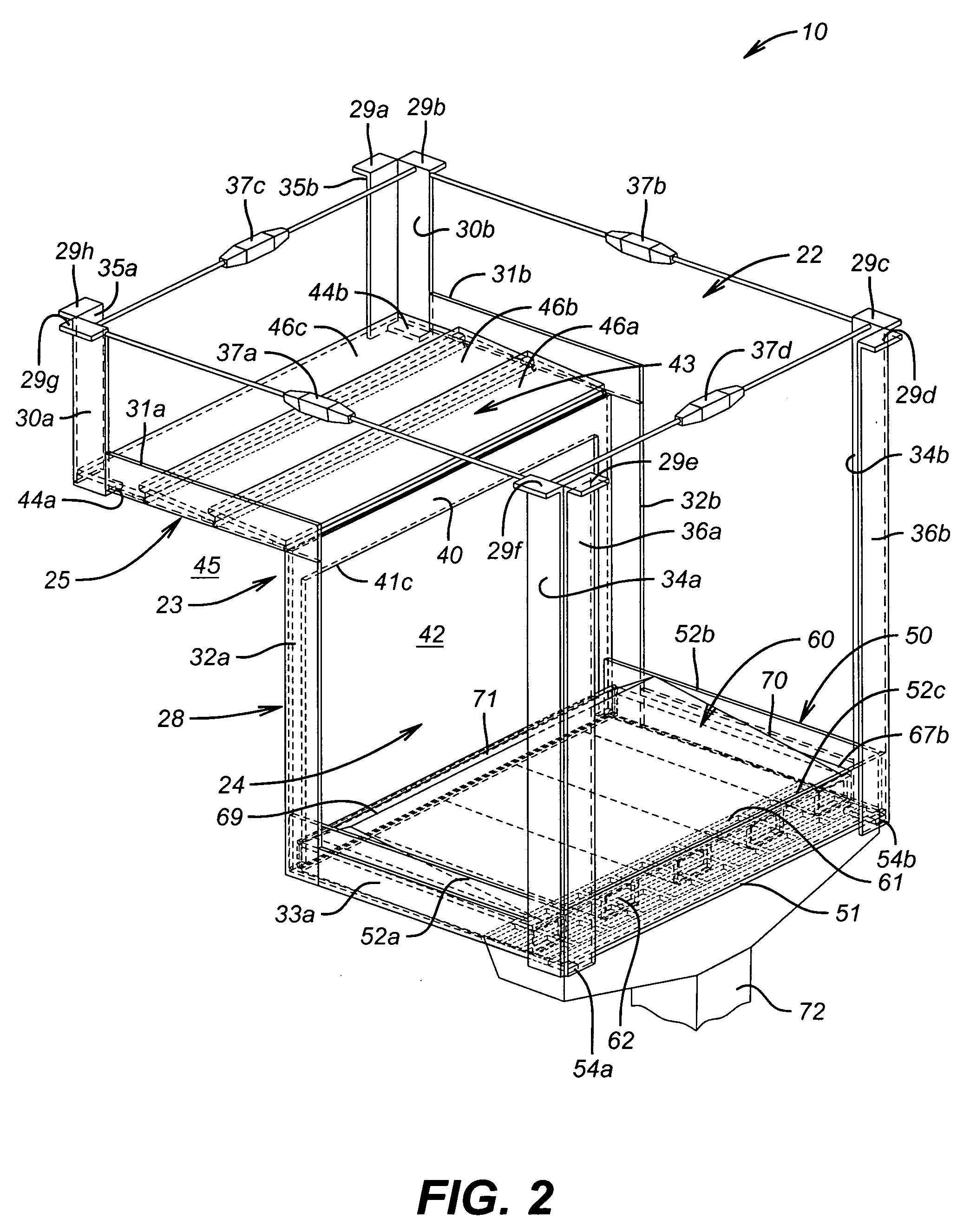
[0031]The concepts embodied in the embodiments described herein have application to any system in which an opening at or near grade level communicates with a ventilation duct for an underground chamber or tunnel or other underground structure requiring ventilation, and through which opening substantial volumes of water can enter, as with heavy rain or street flooding. The embodiments of the invention automatically block downward flow of substantial surface water into an underground ventilation duct communicating upwardly to a ground surface opening. In the following detailed description of embodiments, reference is made to the accompanying drawings, which form a part hereof and in which are shown, by way of illustration, specific embodiments in which the invention may be practiced. Specific details disclosed herein are in every case a non-limiting embodiment representing concrete ways in which the concepts of the invention may be practiced. This serves to teach one skilled in the ar...


PUM


Abstract

Embodiments are described for preventing downward flow of substantial surface water into an underground ventilation duct communicating upwardly to a ground surface opening. The embodiments comprise a support having a top opening and an opening in a lower portion above a floor. The opening in the lower portion is for venting communication with a proximate portion of the ventilation duct. The support supports at least one seat and paired buoyant gate set. The seat is mounted perpendicularly relative to the gate and a portion of a passageway under the seat for fluidly communicating beyond such portion to the top opening of the support and to the proximate portion of the ventilation duct. The buoyant gate is positioned lower than the seat and the passageway, is of sufficient size to block the passageway, and is responsive to water rising in the support by floatingly pivoting upwardly until engaging the seat, thereby blocking the passageway. In an embodiment, the seat of at least one set is mounted under the top opening spaced from one of the opposing sides a horizontal distance nominally equal to a fraction applied to a length for the particular opening, the fraction having the numerator 1 and a denominator which is the sum of 1 plus the number of seat and gate sets, and the buoyant gate has a seat engagement height nominally equal to the same fraction applied to the same opening length.

Description

CROSS-REFERENCE TO RELATED APPLICATIONS[0001]This application claims priority to U.S. provisional application 61 / 011,690, filed Jan. 18, 2008, the entirety of the contents of which are incorporated herein by reference.BACKGROUND OF THE DISCLOSURE[0002]1. Technical Field[0003]This invention relates to fluid control by water gates and more particularly, to pivoted gates responsive to water pressure.[0004]2. Background Art[0005]Prior patents by the present invent or have addressed preventing surface storm waters from entering and flooding lower levels of buildings or underground garages (U.S. Pat. No. 6,623,209) and preventing storm waters from storm sewers back flowing through street gutters into surface streets (U.S. Pat. No. 7,101,114). These inventions do not address the problem of surface storm waters entering and flooding underground tunnels and chambers through ventilation ducts connecting the underground chambers or tunnels to air at ground surface. Such chambers and tunnels in...

Claims


Application Information

Patent Timeline
IPC IPC(8): E02B7/50
CPCE21F1/08
Inventor WATERS, JR., LOUIS A.
Owner FLOODBREAK
Why Eureka
Try Eureka