Jewelry Mandrel and Method of Using the Same

a technology for jewelry and mandrels, which is applied in the direction of transportation and packaging, rigid containers, and other domestic objects, and can solve the problems of jewelry that is and the consumer will feel discomfort when wearing the piece, and the jewelry will be either too large or too small. , to achieve the effect of reducing the risk of injury, and improving the safety of wearers

Inactive Publication Date: 2009-07-30
TERESIAK MACIEJ A
View PDF0 Cites 14 Cited by
  • Summary
  • Abstract
  • Description
  • Claims
  • Application Information

AI Technical Summary

Benefits of technology

[0007]A mandrel and a method of using a mandrel comprising a shaft having an axial groove capable of accepting one end of a metal wire inserted into the axial groove at a selected position, wherein the axial groove has a width and a depth that prevents the end of the metal wire from generally shifting away for the selected position as the wire is wound around a perimeter of a cross-section of the shaft.

Problems solved by technology

A major drawback to current mandrels is the difficulty in holding a metal wire in place as it is tightly wound around the circumference of the mandrel, so that it is bent into the desired shape.
It is important for a piece of jewelry to be sized correctly or the consumer will feel discomfort when wearing the piece because it will either be too tight or too loose.
If the metal wire shifts away from the desired location on the mandrel, the resulting piece of jewelry will be either too large or too small and will require additional bending and shaping of the metal.
Additional bending and shaping creates more imperfections in the surface of the loop, which ultimately requires additional polishing or surfacing resulting in a loss of precious metal.

Method used


Image

  • Jewelry Mandrel and Method of Using the Same
  • Jewelry Mandrel and Method of Using the Same
  • Jewelry Mandrel and Method of Using the Same

Examples


Embodiment Construction

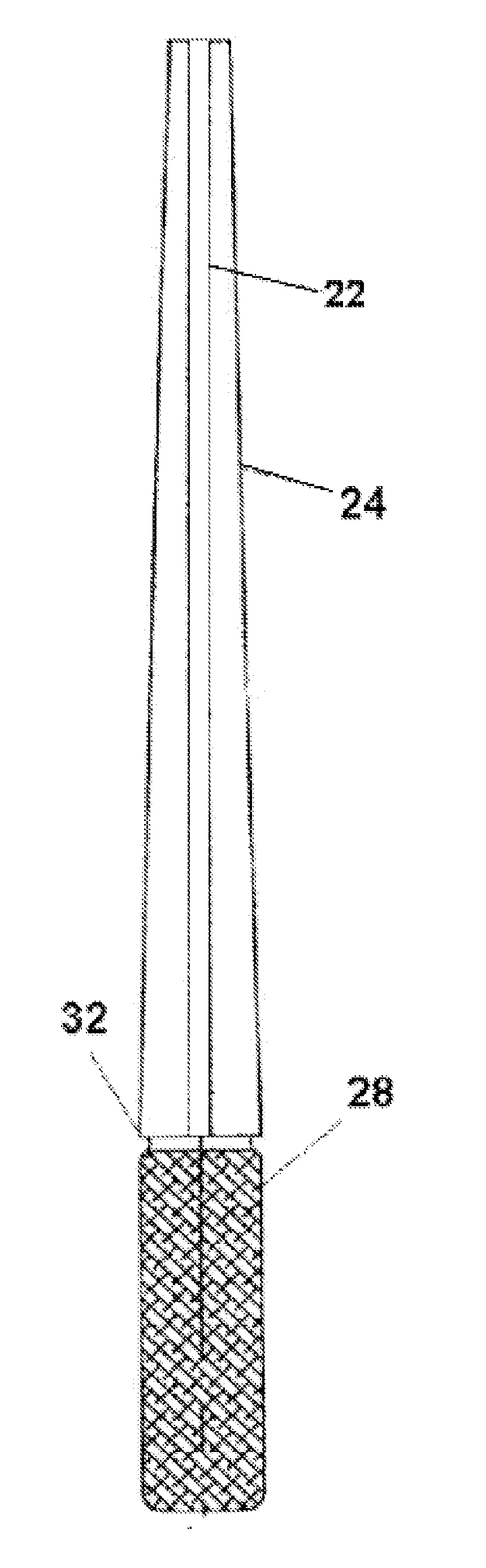
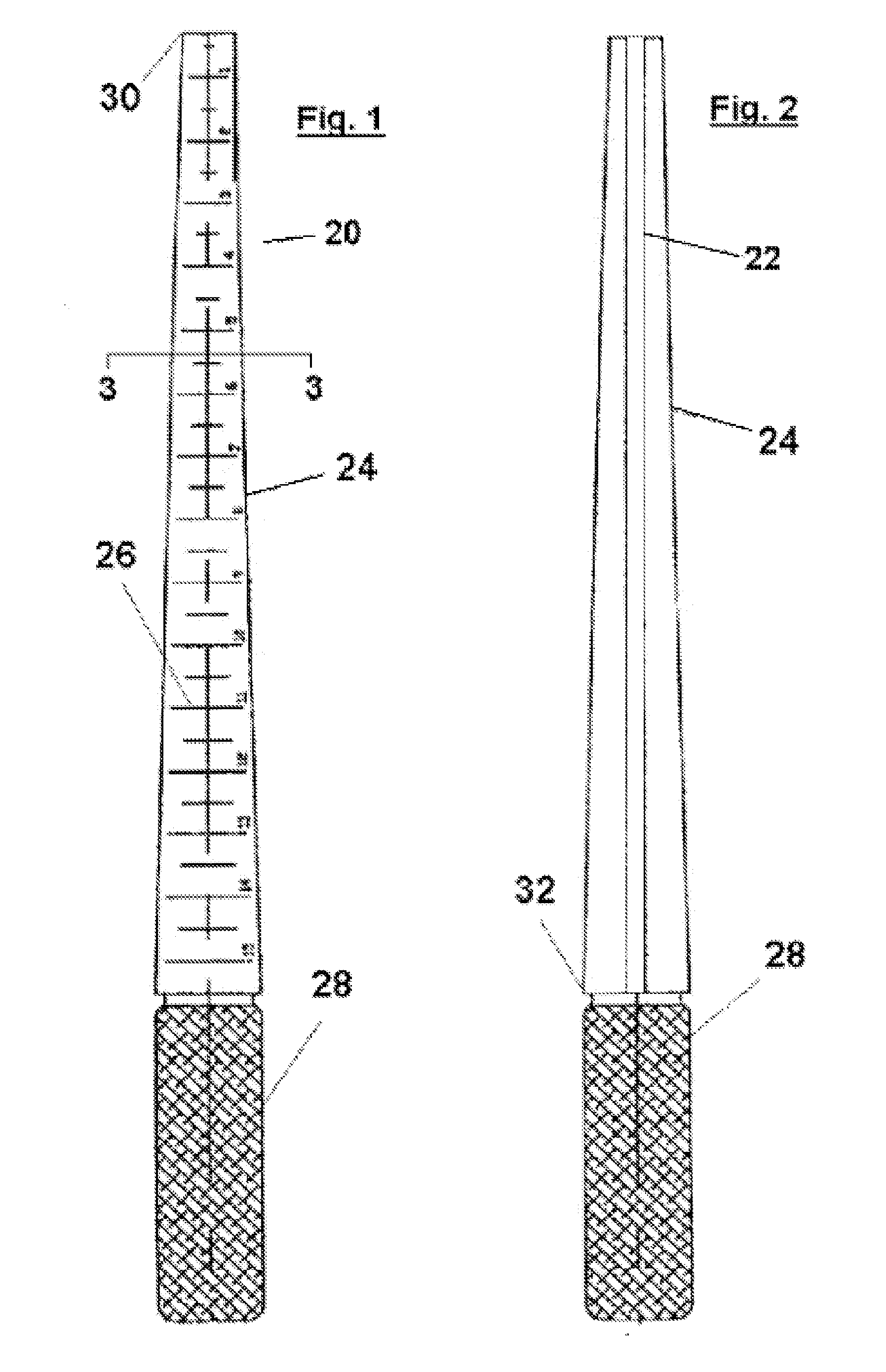
[0021]Referring first to FIG. 1, a front elevational view of a mandrel constructed in accordance with the teachings of the present invention may now be seen. The mandrel 20 comprises a shaft 24 in which the diameter of the shaft 24 increases from the tip 30 to the opposite end at which there is a handle 28 having a generally cylindrical shape. The mandrel 20 may be made of any rigid material, preferably steel, and is also preferably manufactured as a single unitary piece. The present invention is not limited to a shaft which is tapered, but may also be comprised of a shaft having a uniform thickness, which is advantageous for a user that prefers to fabricate multiple loops of the same size on a single mandrel. For tapered mandrels, the surface of the shaft 24 is divided into several gradations 26. In the embodiment of FIGS. 1 and 2, the scale ranges from a size of one to fifteen that is further divided into subdivisions of halves; however, the present invention is not limited to a p...


PUM

PropertyMeasurementUnit
widthaaaaaaaaaa
depthaaaaaaaaaa
lengthaaaaaaaaaa

Abstract

A jewelry mandrel having a tapered shaft with an axial groove in the surface of the shaft. The axial groove is capable of accepting one end of a metal wire at a pre-selected location and the depth and width of the groove are sized, such that the metal wire is not generally displaced axially from the pre-selected location as the wire is wound around the perimeter of a cross-section of the shaft.

Description

FIELD OF THE INVENTION[0001]This invention relates to a device for manufacturing jewelry and a method of using such a device. More particularly, this invention relates to an improved mandrel and method, which can be used by jewelers to fabricate shanks, rings, wedding bands, bangles, or bracelets of various shapes or sizes.BACKGROUND OF THE INVENTION[0002]Jewelers often use mandrels to make hoop-shaped pieces or to determine the size of a piece of jewelry, specifically rings. These tools consist of a tapered rod. The length of the rod is graduated and each gradation is marked with a value. The value of each marking typically indicates a whole, quarter, or half size. Ring mandrels are commonly sold in two sizes. Slender ring mandrels are generally provided for ring sizes ranging from one to fifteen and thicker mandrels are provided for sizes ranging from size fourteen to twenty-eight.[0003]The marking on a ring mandrel reflects a ring size such that the circumference of the rod at th...

Claims


Application Information

Patent Timeline
Patent Type & Authority Applications(United States)
IPC IPC(8): B23P13/00A44C27/00A45C11/16
CPCA44C9/00A44C27/00Y10T29/49588Y10T29/21B21F37/00
Inventor TERESIAK, MACIEJ A.
Owner TERESIAK MACIEJ A
Why Eureka
Try Eureka