
Magnetic Positioning Device

a positioning device and magnetic technology, applied in the direction of work holders, metal-working machine components, manufacturing tools, etc., can solve the problems of random errors, change of selected angles, time-consuming and inefficient setting up of positioning/alignment for the angles of workpieces that are frequently used in the industry, etc., to achieve the effect of quick and efficient operation

Active Publication Date: 2009-07-30
VALTRA
View PDF7 Cites 8 Cited by
  • Summary
  • Abstract
  • Description
  • Claims
  • Application Information

AI Technical Summary

Benefits of technology

[0006]Present invention provides a technical solution for a magnetic positioning device, whereby the angle-setting can be done quickly and efficiently, for the frequently used angles in the industry.
[0007]The implementation of present magnetic position device primarily consists of two magnetic pieces connected by a hinge device which contains a “toothed groove” in addition to the hinge itself, so that it enables easy adjustment of angles, particularly for frequently used angles.

Problems solved by technology

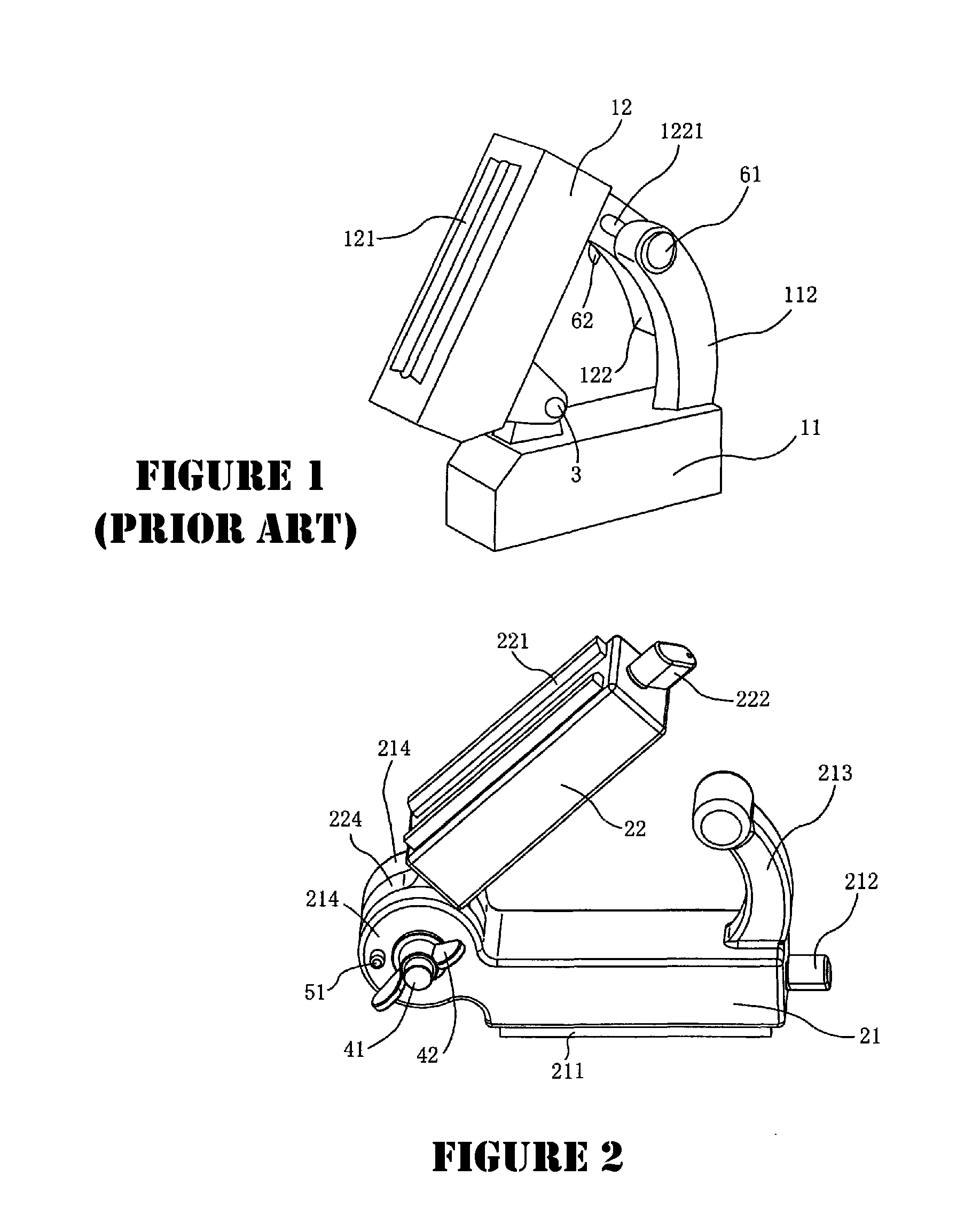
The disadvantages of such prior art device include: in the case where work pieces are big or heavy, locking bolts 61 and nuts 62 tend to loose the tightness as between the two arm pieces 112 and 122, due to continuous weight applied onto the positioning device, resulting in the change of the selected angle.
Moreover, when such prior art device is used on work pieces with varied and changing angles, it is both time-consuming and inefficient to set up the positioning / alignment for the work piece angles that are frequently used in the industry.
Such disadvantages further lead to random errors when the selection and setting of the frequent angles cannot be obtained quickly.

Method used


Image

  • Magnetic Positioning Device
  • Magnetic Positioning Device
  • Magnetic Positioning Device

Examples


Embodiment Construction

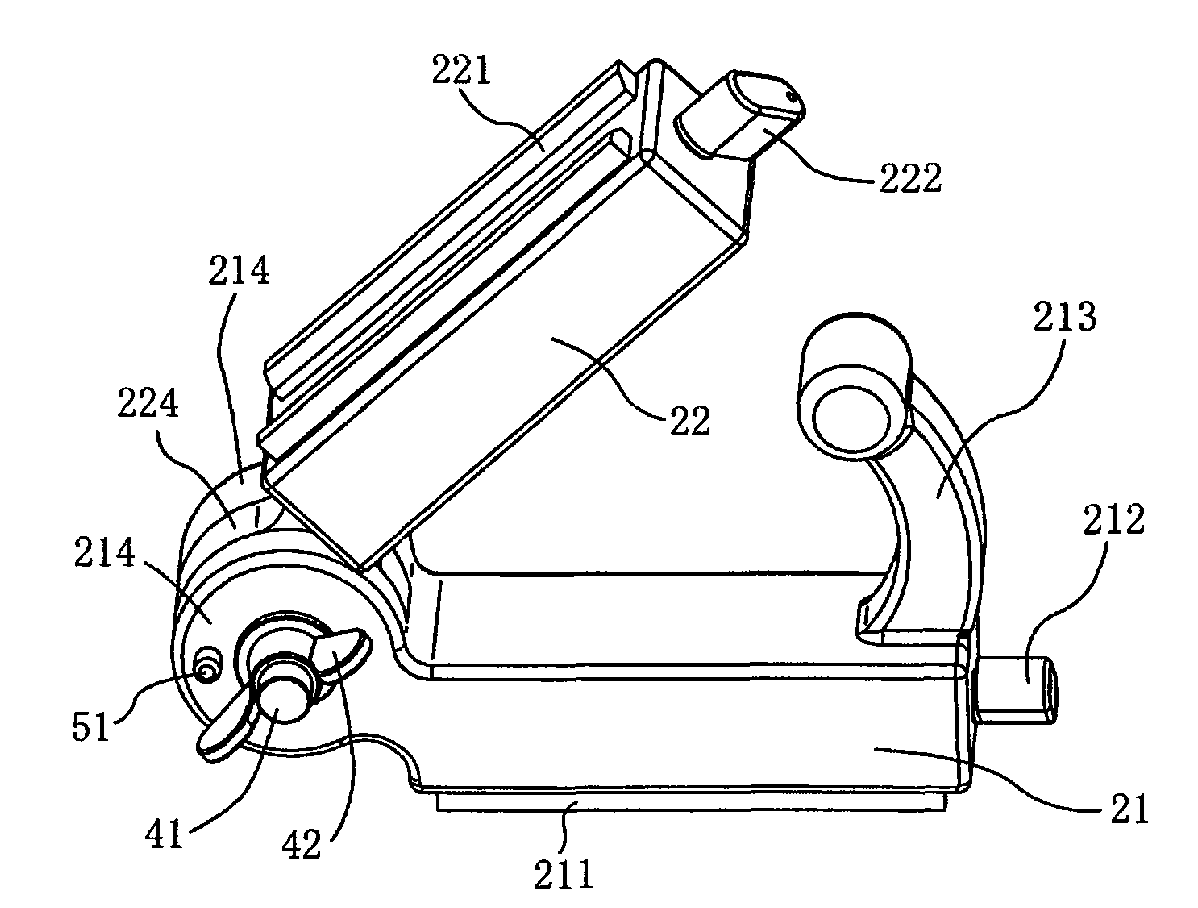
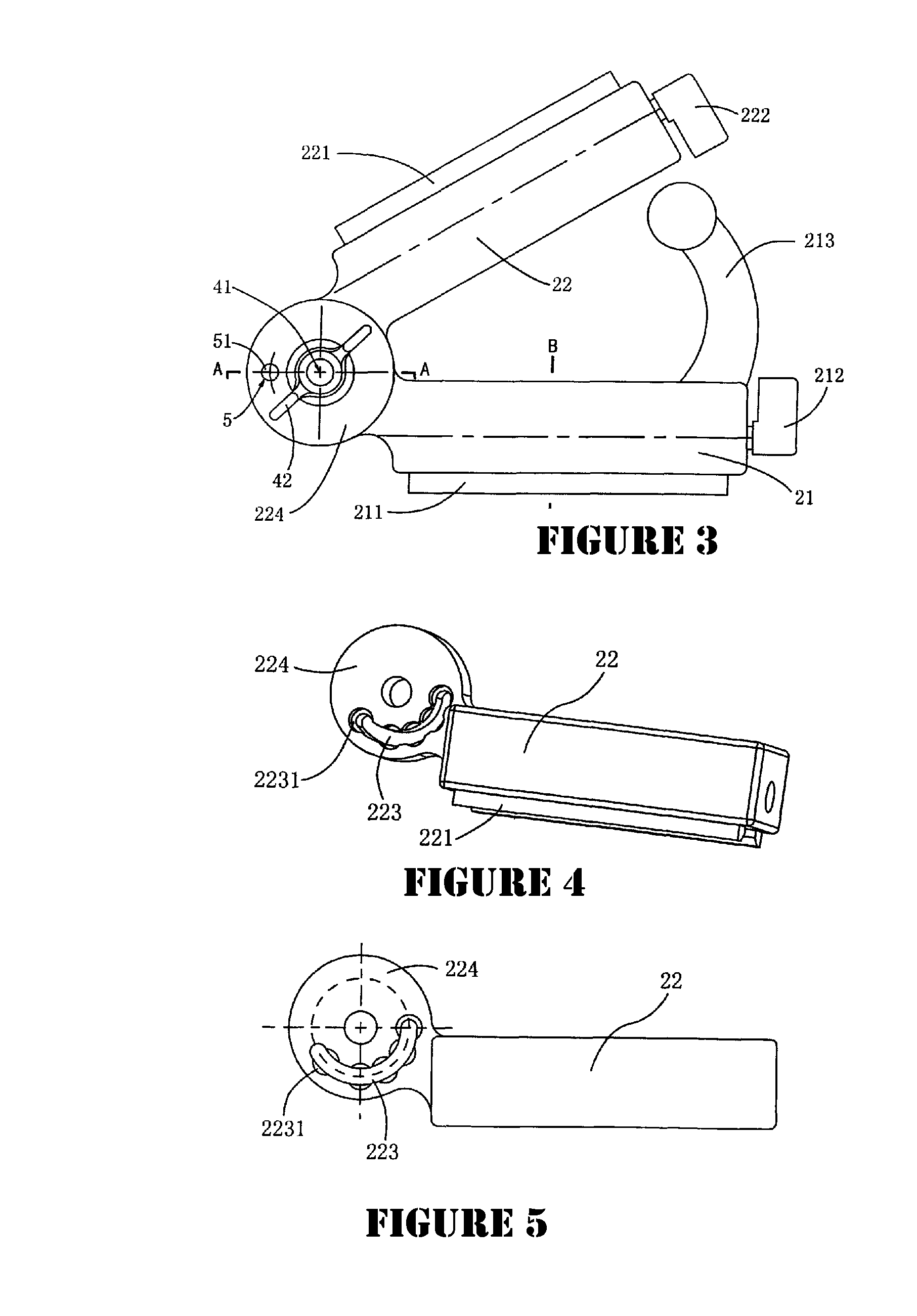
[0021]The magnetic positioning / aligning device disclosed herein and as illustrated in FIGS. 2-9, comprised of a first magnetic arm 21 and a second magnetic arm 22, whereby they are connected by an axle connector 4 on the respective first end of the two magnetic arms 21 / 22.

[0022]Said axle connector 4 is further made up of 2 connecting disks 214 formed at said first end of magnetic arm 21 and one connecting disk 224 formed at said first end of magnetic arm 22, so that disk 224 is sandwiched in-between disks 214, wherein a locking bolt 41 and a corresponding locking nut 42 are inserted through the concentric hole of said connection disks and hingeably attached to the two outside surfaces of the said connecting disks 214 / 224.

[0023]An activation through-hole 5 is formed on one of the connection disks 214. Another hole, shaped like a cul-de-sac, is formed on the other connection disk 214, so that the cul-de-sac hole contains a spring 52 (detailed later). A toothed-groove 223 is formed on ...


PUM


Abstract

A magnetic positioning device is disclosed and claimed wherein two magnetic arms are hingeably connected by an axle connector with locking bolt and nut, and an activation hole with pin inserting through the connection disks having arc-shaped toothed-groove made the selection of frequently used angles straight-forward and easy, when the pre-select angles are built to the “indents” in the toothed-groove, so that the enlarged head on the pin can be used to easily engaging to the selected angle, by pushing toward the spring located inside the hole on the disk. An optional switch is provided on the second end of the magnetic arm for easy control of the magnetic power direction.

Description

CLAIM OF FOREIGN PRIORITY, 35 U.S.C. §119[0001]The present invention claims its foreign priority filing, pursuant to the provision of 35 U.S.C. section 119 et seq, based upon the application filed by the same inventors in China, having application number 200820055121.6 filed on Jan. 25, 2008.FIELD AND BACKGROUND OF THE INVENTION[0002]The present invention relates generally to a positioning device; specifically a device with magnetic attaching power that can be used to position metal work pieces for ease of being worked / operated upon.[0003]Magnetic aligning or positioning tools are widely used for the positioning or aligning of metal work pieces. These tools are mostly made of a single magnetic piece, or two (2) magnetic pieces put together in a certain configuration. Such tools provide a fixed-angle (such as 90-degree fix angle) or adjustable-angle device made from two magnetic pieces hinged together by an axle-connection.[0004]A prior art example of Eclipse Tools' heavy duty variab...

Claims


Application Information

Patent Timeline
Patent Type & Authority Applications(United States)
IPC IPC(8): B25B11/00
CPCB25B11/002B23Q3/1546
Inventor WONG, HARRYZHAO, DAMING
Owner VALTRA
Learn More