Float-type energy-generating system

a technology of energy generation system and floating structure, which is applied in the direction of special-purpose vessels, marine propulsion, vessel construction, etc., can solve the problems of high potential of fft system, limited fft system setting, and inability to meet all the energy needs of this country by using only on-land wind turbines. system, reduce system's speed, system can sail smoothly

Active Publication Date: 2009-07-30
TERAO YUTAKA
View PDF1 Cites 21 Cited by
  • Summary
  • Abstract
  • Description
  • Claims
  • Application Information

AI Technical Summary

Benefits of technology

[0032]In the invention, the water turbine has a cross-section that enables the resistance of water to the water turbine and to the hull to be minimized, and therefore the system can sail smoothly. If the water turbine's diameter is large, the water turbine decreases the system's sailing speed. At that time, the revolution of the propeller is slow due to the resistance of the water, while the resistance that the system encounters is small. In contrast, if the water turbine's diameter is small, the sailing speed when the system receives the wind is increased. At that time, the turbine's blade revolves fast, because the resistance of the water is low, while the resistance that the system encounters increases. A water turbine of optimal diameter can be selected.

Problems solved by technology

However, it is not realistic to meet all the energy needs of this country by using only on-land wind turbines, because wind turbines set up for that purpose would occupy one-fourth of this nation's land.
Although the areas where FFT systems can be set are limited due to the wind environment on the seas, FFT systems have high potential because of their low technical barriers.
An FFT system is not efficient in generating power in such areas, because winds in such areas are not constant throughout the year.
However, due to financial cost-benefit considerations, the floating bodies on which wind-power-generation devices are mounted are very long, reaching a length of 2 km.
Another problem of SMFT systems is that it is difficult to find a maintenance base for an SMFT system.
Accordingly, the vessel weaves in a strong wind, and therefore the invention of Patent Document 1 is not highly efficient in generating energy.
Moreover, Patent Documents 2 and 3 (generating energy by using a combination of wind-powered generators and water-powered generators) also might not be highly efficient in generating energy, because those inventions have problems in that the direction in which the vessel advances is against the prevailing wind or ocean current.

Method used


Image

  • Float-type energy-generating system
  • Float-type energy-generating system
  • Float-type energy-generating system

Examples


embodiment 1

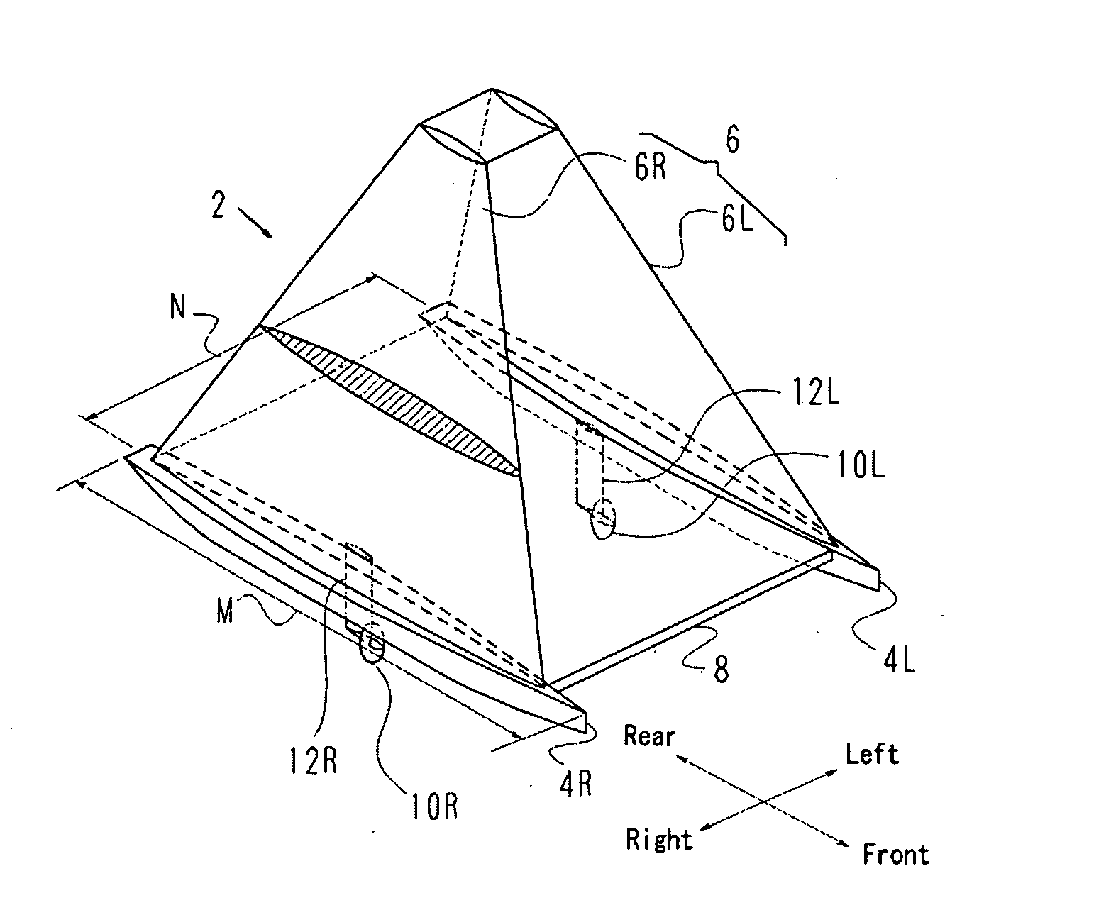
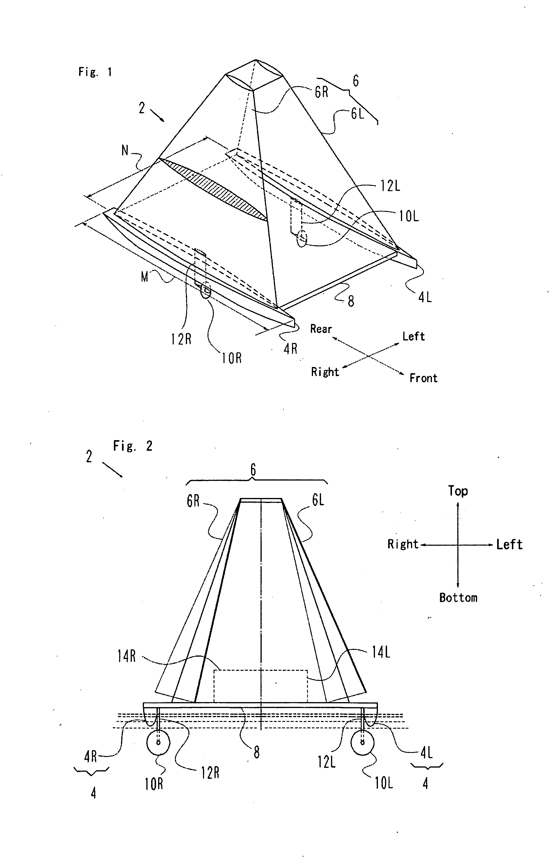
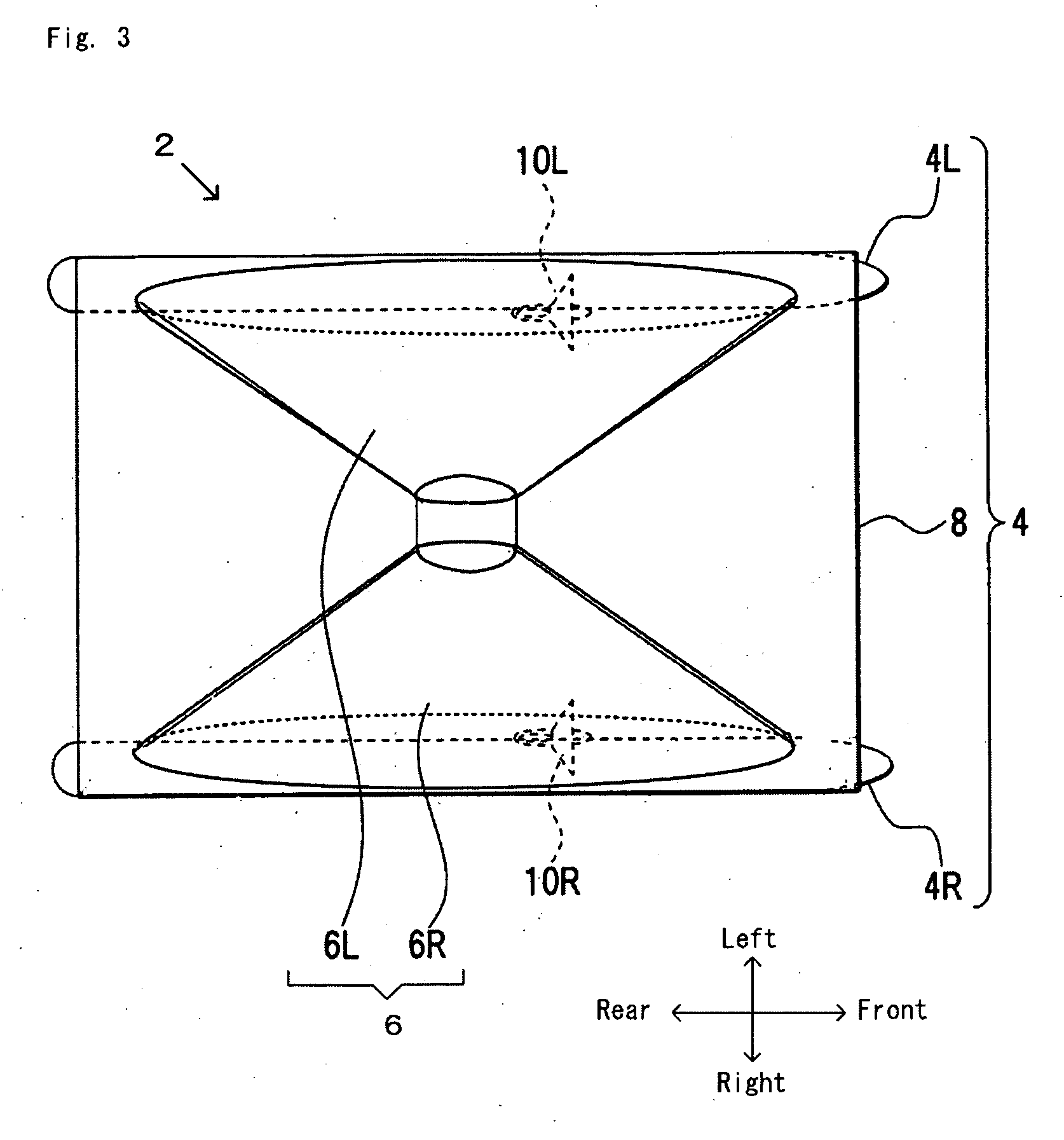
[0067]The first embodiment of the present invention is shown by FIGS. 1-6. FIG. 1 is a perspective view of a float-type energy-generating system, FIG. 2 is an elevation view of the system shown in FIG. 1, FIG. 3 is a top view of the system shown in FIG. 1, FIG. 4 is a side elevation view of the system shown in FIG. 1, and FIG. 5 shows one example of the configuration of a water turbine. FIG. 6 is a block diagram of a power generator. The same reference numbers in different figures represent the same components.

[0068]As shown in FIGS. 1 to 4, the float-type energy-generating system 2 includes a hull 4 that allows the system to be suspended underwater or to float on water, and a plate 6 that receives wind at sea so as to allow the hull 4 to sail. The hull 4 is configured as, for example, a catamaran wherein the system includes a starboard-side body 4R and a larboard-side body 4L, and a deck 8 that covers the starboard-side body 4R and larboard-side body 4L and the space between them. ...

embodiment 2

[0075]The second embodiment of the present invention will now be described, with reference to FIGS. 7-10. FIG. 7 is a perspective view of a float-type energy-generating system, FIG. 8 is an elevation view of the system of FIG. 7, FIG. 9 is a side elevation view of the system of FIG. 7, and FIG. 10 is a top view of the system of FIG. 7. The same components that are present in FIGS. 7-10 as well as in FIGS. 1-6 have the same reference numbers in FIGS. 7-10 as they have in FIGS. 1-6.

[0076]As shown in FIGS. 7-10, the float-type energy-generating system 2 includes a hull 4 that allows the system to be suspended underwater or to float on seawater, and a plate 6 that receives wind at sea so as to allow the hull 4 to sail. The configuration of the hull 4 is not illustrated here because it is the same as that of Embodiment 1. The plate 6 can be configured in the same manner as in Embodiment 1 in that its horizontal cross-section can have a streamlined shape, can be manufactured to have a rig...


PUM


Abstract

The objective of the invention is to provide a float-type energy-generating system that is able to maintain the system's body stably, without listing, while sailing, even in a strong wind, while efficiently generating electricity. The system includes a hull (4) that allows the system to be suspended underwater or to float on seawater, one or more plates (6) that receive the sea wind so as to allow the hull to sail, and one or more power generators (3) that generate electricity by rotating one or more water turbines that use water as a working medium while the hull sails.

Description

CROSS-REFERENCE TO RELATED APPLICATIONS[0001]The present application is based on International Application No. PCT / JP2007 / 061663, filed on Jun. 8, 2007, which in turn corresponds to Japanese Application No. 2006-159628 filed on Jun. 8, 2006, and priority is hereby claimed under 35 USC § 119 based on these applications. Each of these applications are hereby incorporated by reference in their entirety into the present application.TECHNICAL FIELD[0002]The present invention relates to a energy-generating system that uses wind force on the sea, and more specifically relates to a float-type energy-generating system that captures electrical energy resulting from the rotation of water turbines under water, while the hull(s) to which the system is attached is / are propelled by wind power so that said water turbines are rotated.BACKGROUND ART[0003]As shown in FIG. 17, a forecast of energy consumption and resources supply indicates that all fossil carbon fuel will be exhausted before 2060 if cu...

Claims


Application Information

Patent Timeline
Patent Type & Authority Applications(United States)
IPC IPC(8): F03D9/00
CPCB60L8/00Y02E10/72B63B35/00B63B2035/446B63B2035/4466B63H9/0607B63J3/02F03B13/10F03B17/061F03D9/00F05B2240/931F05B2240/95H02P9/04Y02E10/22Y02E10/28Y02T10/642Y02T10/7083H02P2101/10H02P2101/15B60L2260/54B63H9/061Y02E10/20Y02T10/64Y02T10/7072Y02E10/30B63J2003/046
Inventor TERAO, YUTAKA
Owner TERAO YUTAKA
Why Eureka
Try Eureka