Thermal module

a technology of thermal modules and modules, applied in the field of thermal modules, can solve the problems of time-consuming and laborious, time-consuming to remove the thermal module from the cpu for repair or cleaning, and the user cannot assemble the thermal module to or remove the thermal module from the cpu without using an appropriate tool, etc., and achieve the effect of convenient assembly to or removal

Active Publication Date: 2009-07-30
ASUSTEK COMPUTER INC
View PDF14 Cites 0 Cited by
  • Summary
  • Abstract
  • Description
  • Claims
  • Application Information

AI Technical Summary

Benefits of technology

[0007]Accordingly, the present invention is directed to a thermal module including a heat sink that can be conveniently assembled to or removed from a heat source on a circuit board.

Problems solved by technology

Therefore, the period of the assembly of the thermal module on the CPU would be time-consuming.
Certainly, it is also time-consuming to remove the thermal module from the CPU for repair or cleaning.
In addition, the user cannot assemble the thermal module to or remove the thermal module from the CPU without using an appropriate tool.
Therefore, it is inconvenient to assemble and remove the thermal module.

Method used


Image

  • Thermal module
  • Thermal module
  • Thermal module

Examples


Embodiment Construction

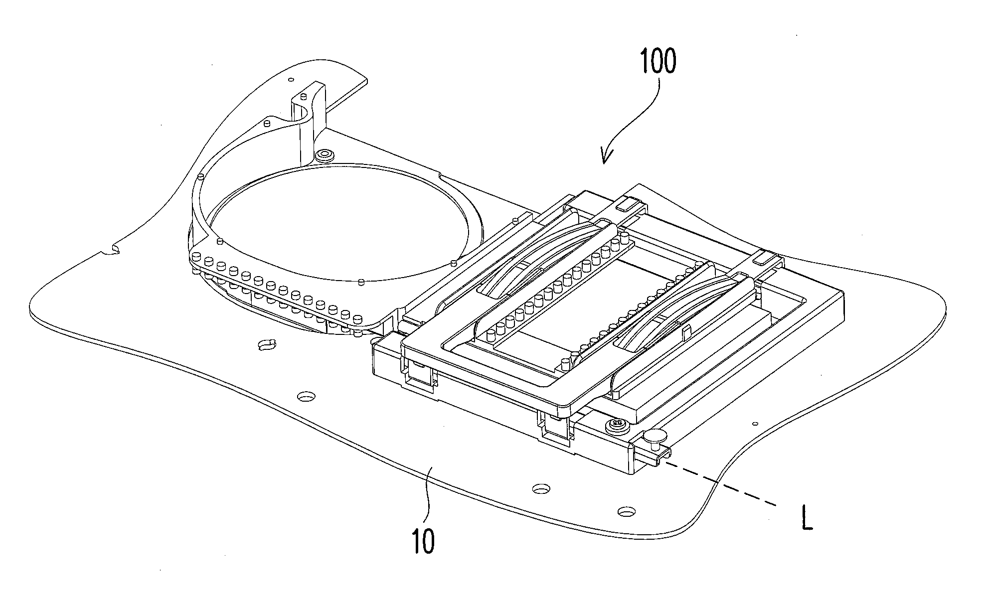
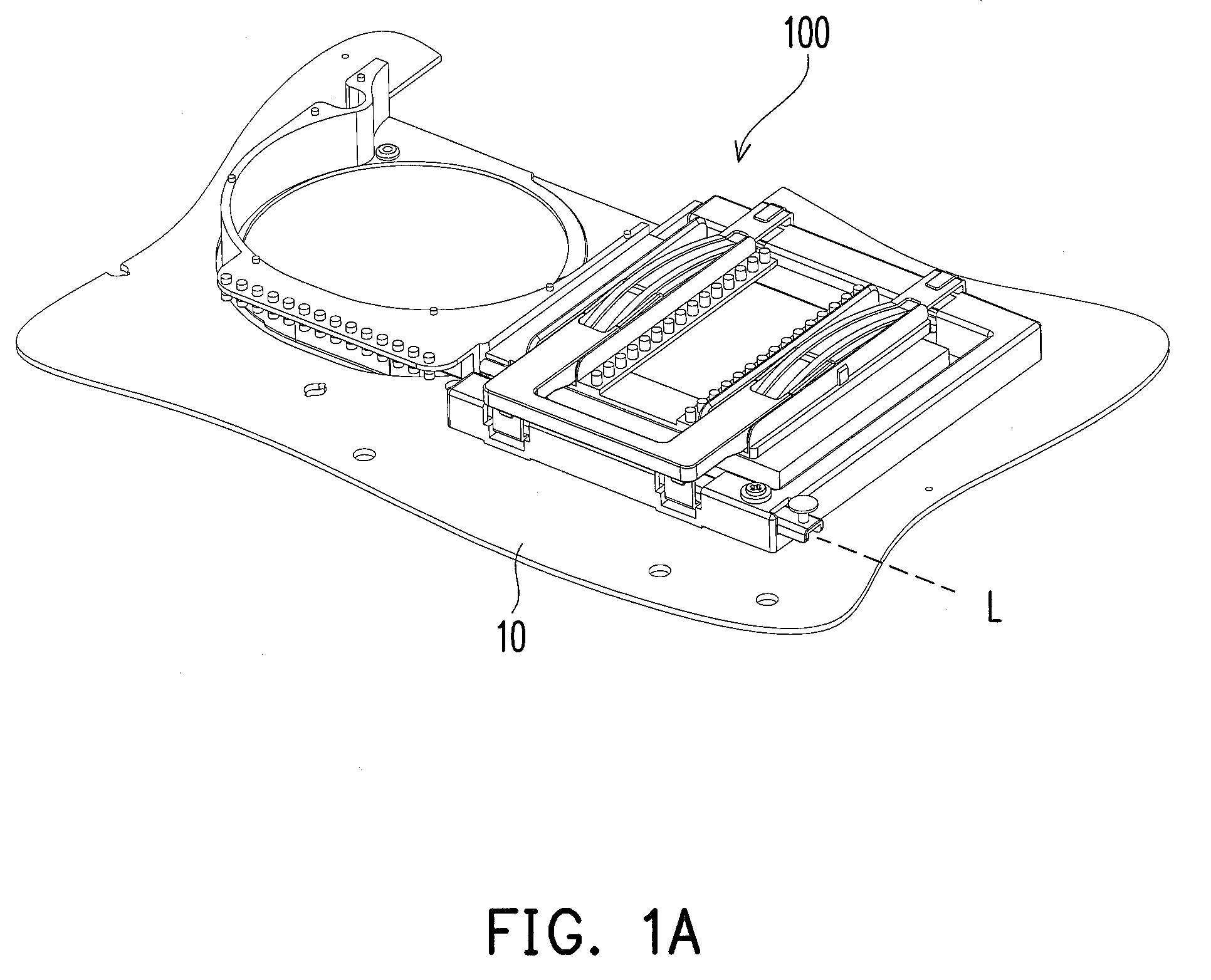
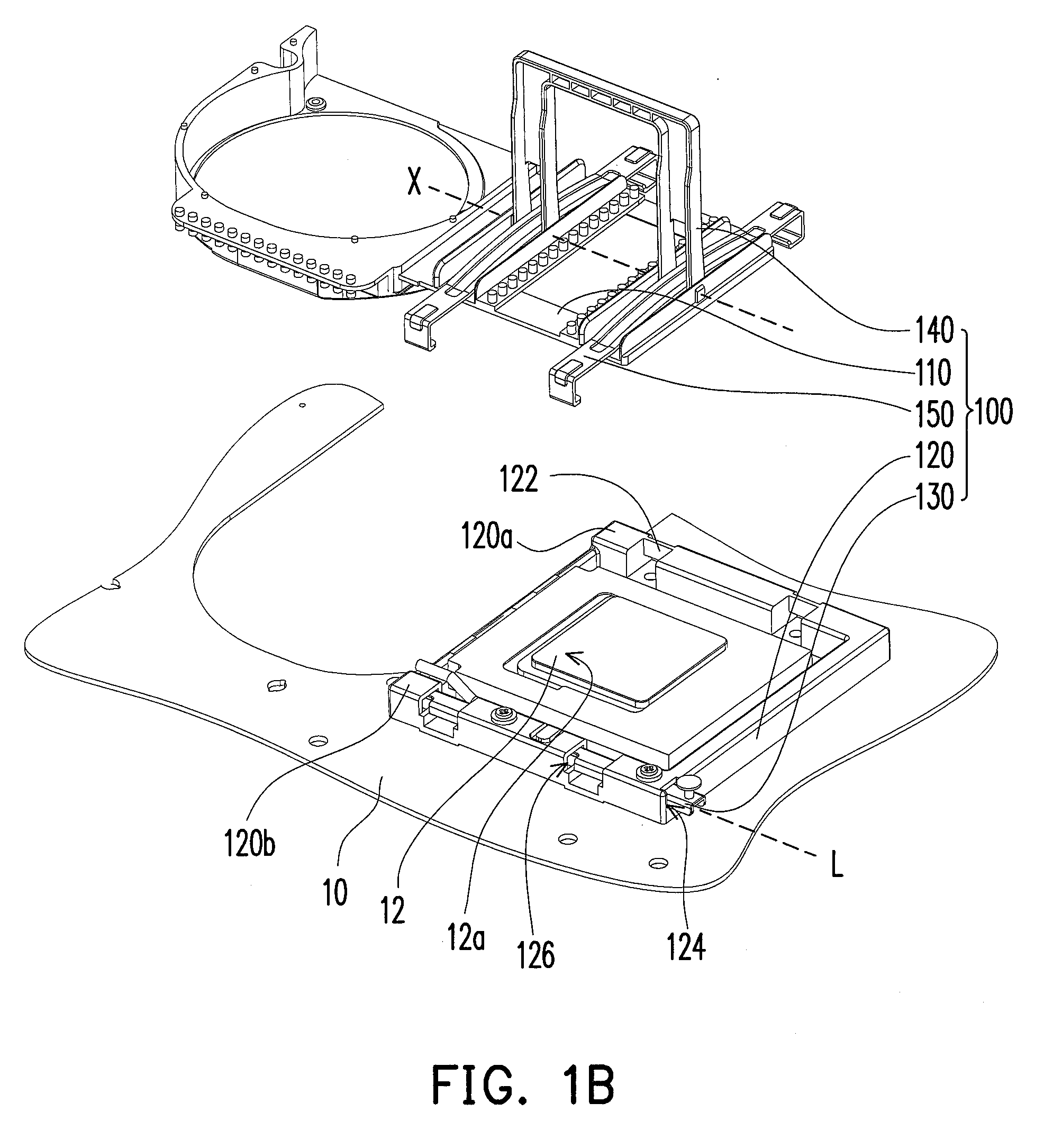
[0026]FIG. 1A illustrates a thermal module assembled on a heat source of a circuit board according to one embodiment of the present invention. FIG. 1B is a partially exploded view of the thermal module and the circuit board of FIG. 1A. Referring to FIGS. 1A and 1B, the thermal module 100 of the present embodiment is suitable for being disposed on a heat source 12 of a circuit board 10 to cool the heat source 12. The thermal module 100 includes a heat sink 110 that can be easily assembled to or removed from the heat source 12. The structure of the thermal module 100 and how the heat sink 110 is assembled to or removed from the circuit board 10 are described in detail below.

[0027]FIG. 2 is an exploded view of the thermal module of FIG. 1A. Referring to FIG. 1B and FIG. 2, the thermal module 100 of the present embodiment mainly includes the heat sink 110 disposed on a contact surface 12a of the heat source 12, a mounting bracket 120, a fastening member 130, a pressing member 140, and a...


PUM


Abstract

A thermal module includes a heat sink disposed on a contact surface of the heat source, a mounting bracket having first and second ends, a fastening member, a pressing member, and at least one clip. The mounting bracket surrounds the heat source. The first end has at least one latch portion. The second end has at least one mounting slot and at least one first opening in communication with the mounting slot. The fastening member is slidably mounted in the mounting slot. The clip spans the heat sink and has two ends respectively engaged with the latch portion and a portion of the fastening member respectively. The pressing member includes a pressing tightly engaged with the clip and urges the heat sink when an operation portion of the pressing member is rotated from the first predetermined position to the second predetermined position.

Description

CROSS-REFERENCE TO RELATED APPLICATION[0001]This application claims the priority benefit of Taiwan application serial no. 97103469, filed on Jan. 30, 2008. The entirety of the above-mentioned patent application is hereby incorporated by reference herein and made a part of specification.BACKGROUND OF THE INVENTION[0002]1. Field of the Invention[0003]The present invention generally relates to a thermal module, and more particularly, to a thermal module that can be easily assembled or removed.[0004]2. Description of Related Art[0005]Following the rapid advance of technology, the operating speed of electronic devices, such as the central processing unit (CPU) of a computer device, has been continuously increased in recent years. As the operating speed increases, the amount of heat generated by the CPU is increased accordingly. To prevent temporary or permanent failure of the computer device due to overheat, the computer device must have sufficient heat dissipating capacity to ensure the...

Claims


Application Information

Patent Timeline
Patent Type & Authority Applications(United States)
IPC IPC(8): H05K7/20
CPCH01L23/4093H01L2924/0002H01L2924/00
Inventor LIN, TZU-WEILIN, JUI-YILU, KUAN-YINGLI, CHIEN-YI
Owner ASUSTEK COMPUTER INC
Why Eureka
Try Eureka