
System and method for managing radio link failures

a radio link and failure technology, applied in the field of wireless communication systems, can solve the problems of inability to meet the needs of lte,

Active Publication Date: 2009-07-30
TEXAS INSTR INC
View PDF7 Cites 65 Cited by
  • Summary
  • Abstract
  • Description
  • Claims
  • Application Information

AI Technical Summary

Benefits of technology

The present invention provides a wireless transmit / receive unit (WTRU) and a method for handover between base stations in a wireless communication system. The WTRU can adjust its operation mode based on a handover command from a first base station and can re-establish the first communication link if the handover fails. The technical effect of the invention is to improve the reliability and stability of wireless communication during handovers between base stations.

Problems solved by technology

However, the use OFDMA and FDMA typically requires changes in handover procedures and related operations.
Specifically, while in IS-95 / CDMA2000 systems (based on CDMA technology) it is possible to have soft handovers (make a connection with a new base station before breaking connection with the current base station), this is not possible in LTE.
However, these proposed LTE systems typically do not provide robust procedures for managing radio link interruptions and / or failures during handover and other communications processes.
However, in some cases, motion of the WRTU or external factors, such as weather conditions, interference from surrounding objects, or interference from other electrical messages, can interrupt the handover process.
Therefore, in such cases, a WRTU may need to stop the handover process and revert to the source eNB or may lose a connection altogether and require reconnection to a communications system.
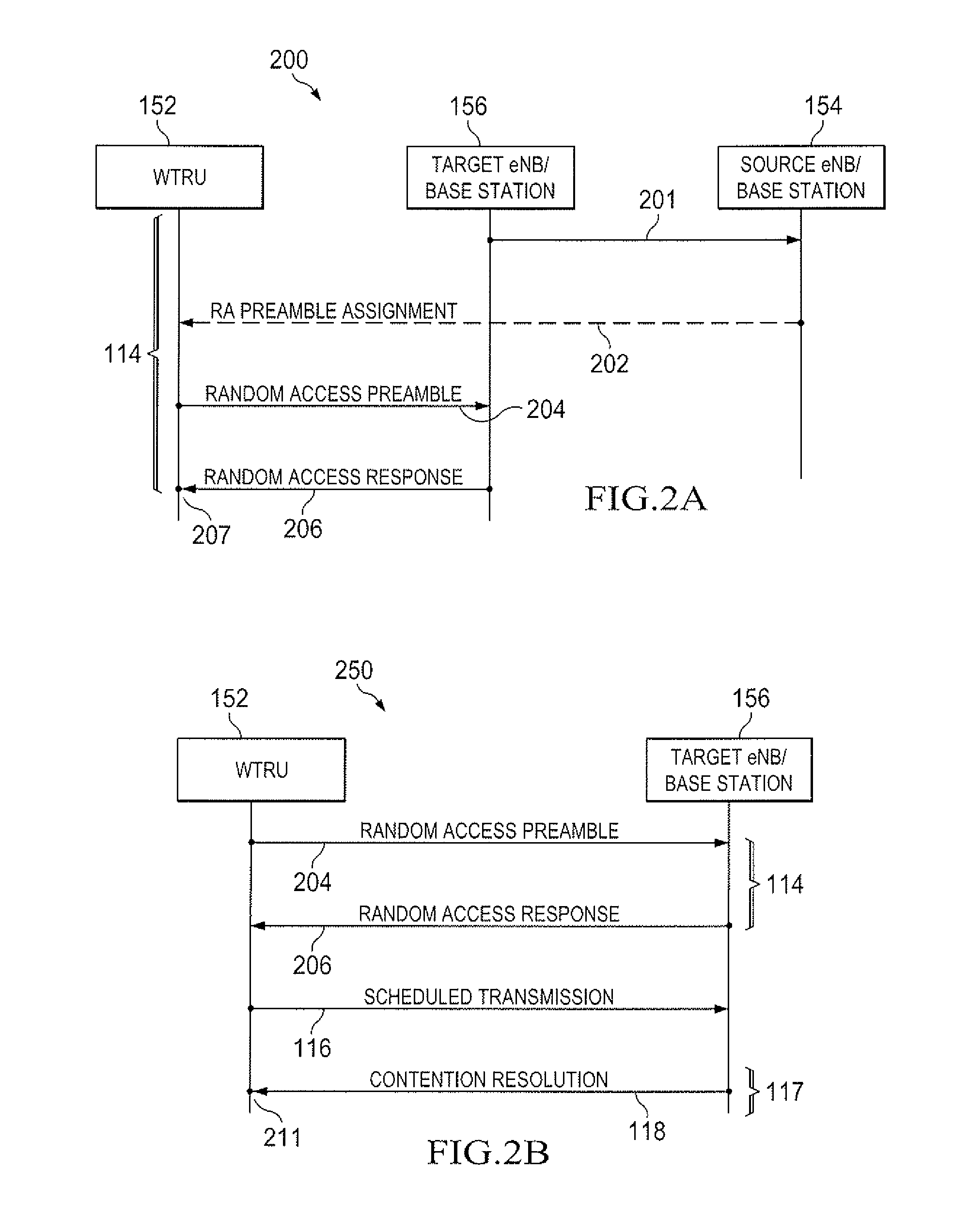
By way of example and not by way of limits, a failure can be caused by the target eNB 156 failing to detect the random access preamble message and consequently failing to generate the random access response message.
However, the radio link failure recovery process is also generally limited in time.

Method used


Image

  • System and method for managing radio link failures
  • System and method for managing radio link failures
  • System and method for managing radio link failures

Examples


Embodiment Construction

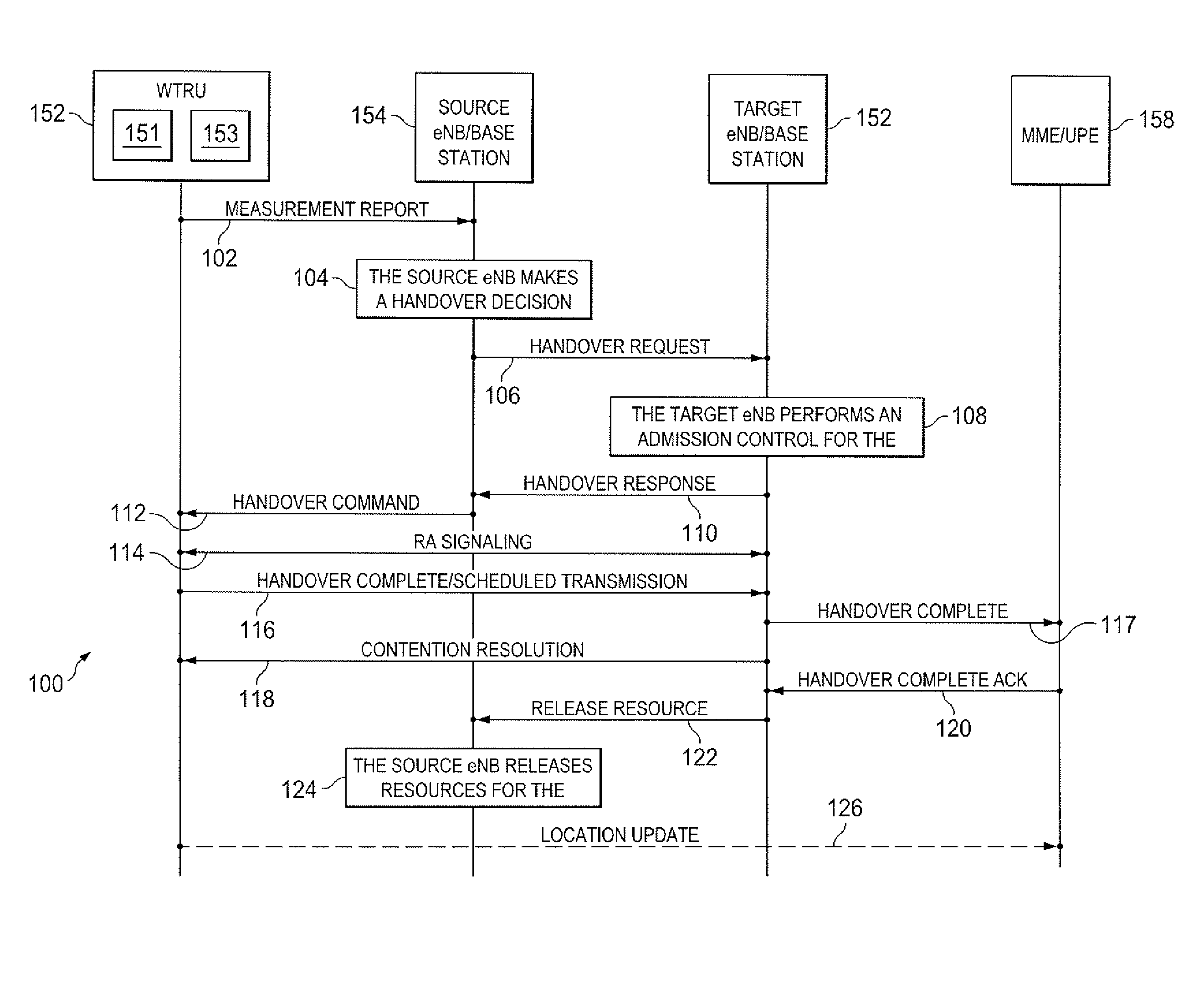
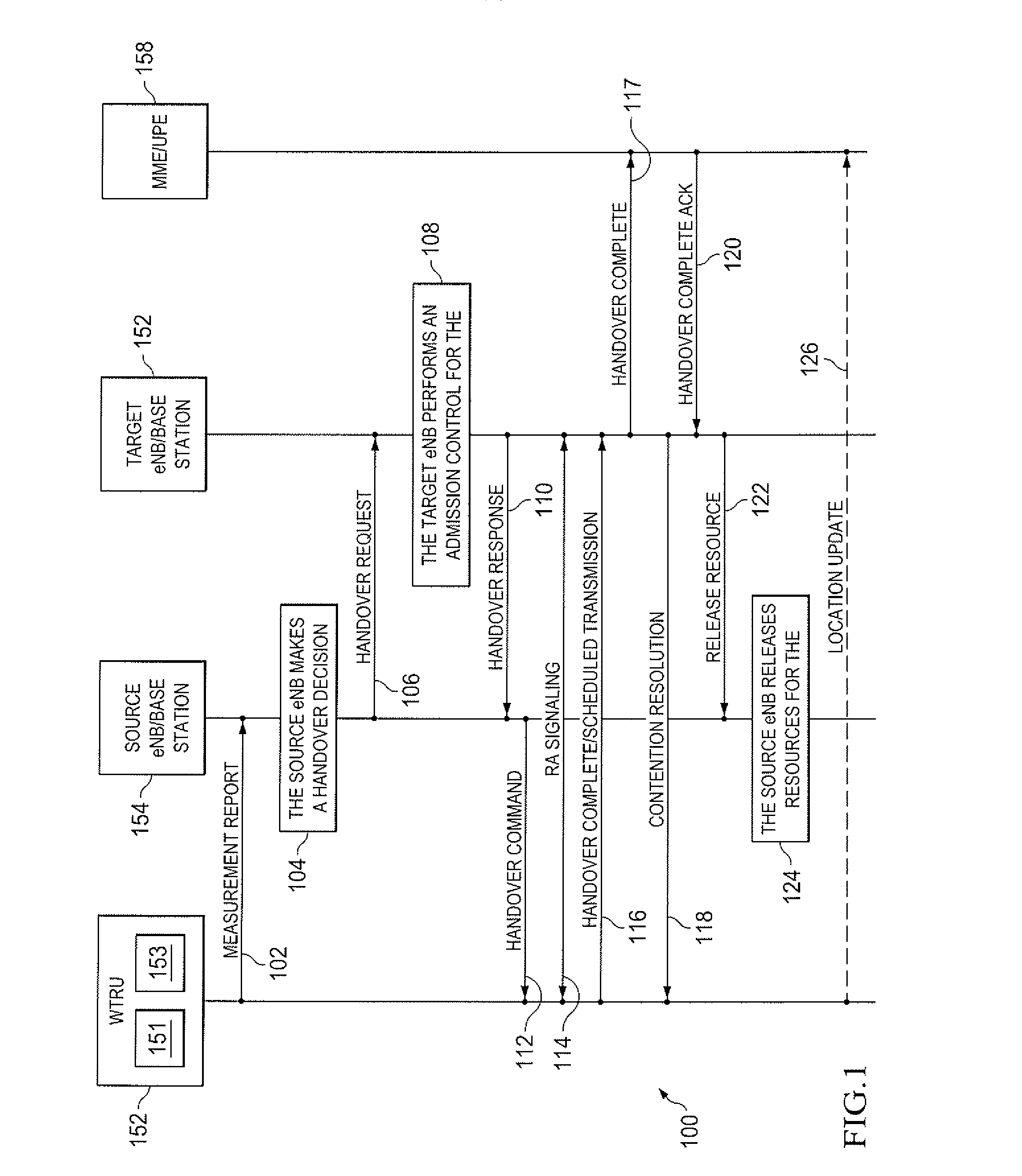
[0012]The present invention is described with reference to the attached figures, wherein like reference numerals are used throughout the figures to designate similar or equivalent elements. The figures are not drawn to scale and they are provided merely to illustrate the instant invention. Several aspects of the invention are described below with reference to example applications for illustration. It should be understood that numerous specific details, relationships, and methods are set forth to provide a full understanding of the invention. One having ordinary skill in the relevant art, however, will readily recognize that the invention can be practiced without one or more of the specific details or with other methods. In other instances, well-known structures or operations are not shown in detail to avoid obscuring the invention. The present invention is not limited by the illustrated ordering of acts or events, as some acts may occur in different orders and / or concurrently with o...


PUM


Abstract

A wireless transmit / receive unit (WTRU) (152) in a wireless communications system includes a transceiver (153) for transmitting and receiving data from a plurality of base stations (154, 156, 357) and a controller (151) communicatively coupled to the transceiver (153) and configured to adjust an operation mode of the transceiver (153). In the WTRU (152), adjusting comprises configuring the transceiver (153) to begin a radio link handover procedure responsive to receiving a handover (HO) command from a first of the plurality of base stations (154, 156, 357) over a first communications link, specifying a first time, and reconfiguring the transceiver (153) to begin a radio link interruption procedure responsive to an expiry of the first time prior to completion of the radio link handover procedure. In the WTRU (152), the radio link interruption procedure first attempts to re-establish the first communications link.

Description

CROSS REFERENCE TO RELATED APPLICATIONS[0001]This application claims the benefit of U.S. provisional application No. 61 / 023,704 filed Jan. 25, 2008 and entitled “Consistent Radio Link Failure Procedure”, which is incorporated by reference as if fully set forth herein.FIELD OF THE INVENTION[0002]The present invention is related to wireless communication systems. More particularly, the present invention is related to a method and system for managing radio link failures in wireless systems.BACKGROUND[0003]Long term evolution (LTE) is now being considered for next generation (3.9G) communications system for developing a new radio interface and radio network architecture that provides a high data rate, low latency, packet optimization, and improved system capacity and coverage. For proposed LTE systems, instead of using code division multiple access (CDMA), which is currently being used in 3G systems, orthogonal frequency division multiple access (OFDMA) and single-carrier frequency divi...

Claims


Application Information

Patent Timeline
Patent Type & Authority Applications(United States)
IPC IPC(8): H04Q7/20H04M1/00
CPCH04W36/18H04W36/08H04W36/0055H04W36/00695
Inventor DU, SHUBHADRA, SANDEEPKANGUDE, SHANTANUVEDANTHAM, RAMANUJA
Owner TEXAS INSTR INC
Learn More