
Implantable distraction osteogenesis device and methods of using same

Inactive Publication Date: 2009-07-30
RGT UNIV OF MICHIGAN
View PDF16 Cites 133 Cited by
  • Summary
  • Abstract
  • Description
  • Claims
  • Application Information

AI Technical Summary

Benefits of technology

[0013]According to another feature, the device may further compr

Problems solved by technology

The main criticisms of external apparatuses are unsightly scars and / or injuries to the facial nerve resulting from the transcutaneous pins, and thus lack of acceptance by the patients (Schmelzeisen R, Neumann G, Von der Fecht R.: Distraction osteogenesis in the mandible with a motor-driven plate: a preliminary animal study, Brit J of Oral Maxil Surg 34:375-378, 1996.
In both external and internal devices, however, the actuation of distraction process relies upon manual length adjustment under patients' compliance, introducing inconvenience and potential error in the procedure.
(2005) showed that continuous osteodistraction resulted in intramembraneous regeneration of bone, whereas intermittent osteodistraction (used by all present distraction devices) caused chondroid ossification in the regenerate of bone.
Those empirical data have shown lower rates of distraction tend to cause mechanical problems (pin loosening, breakage) in devices, while higher distraction rates lead to premature ossification of the callus during distraction osteogenesis (Meyer et al., 2004).

Method used


Image

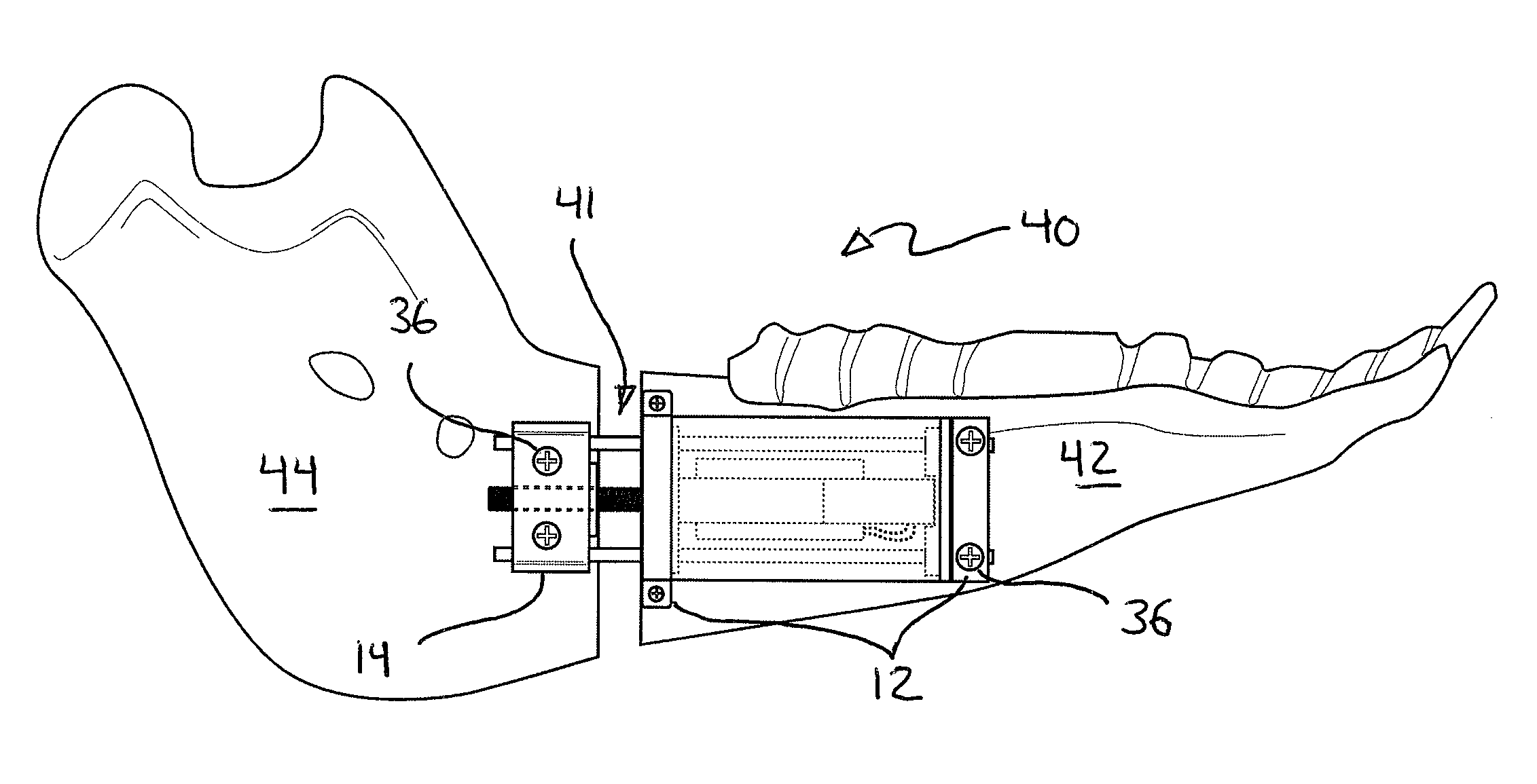
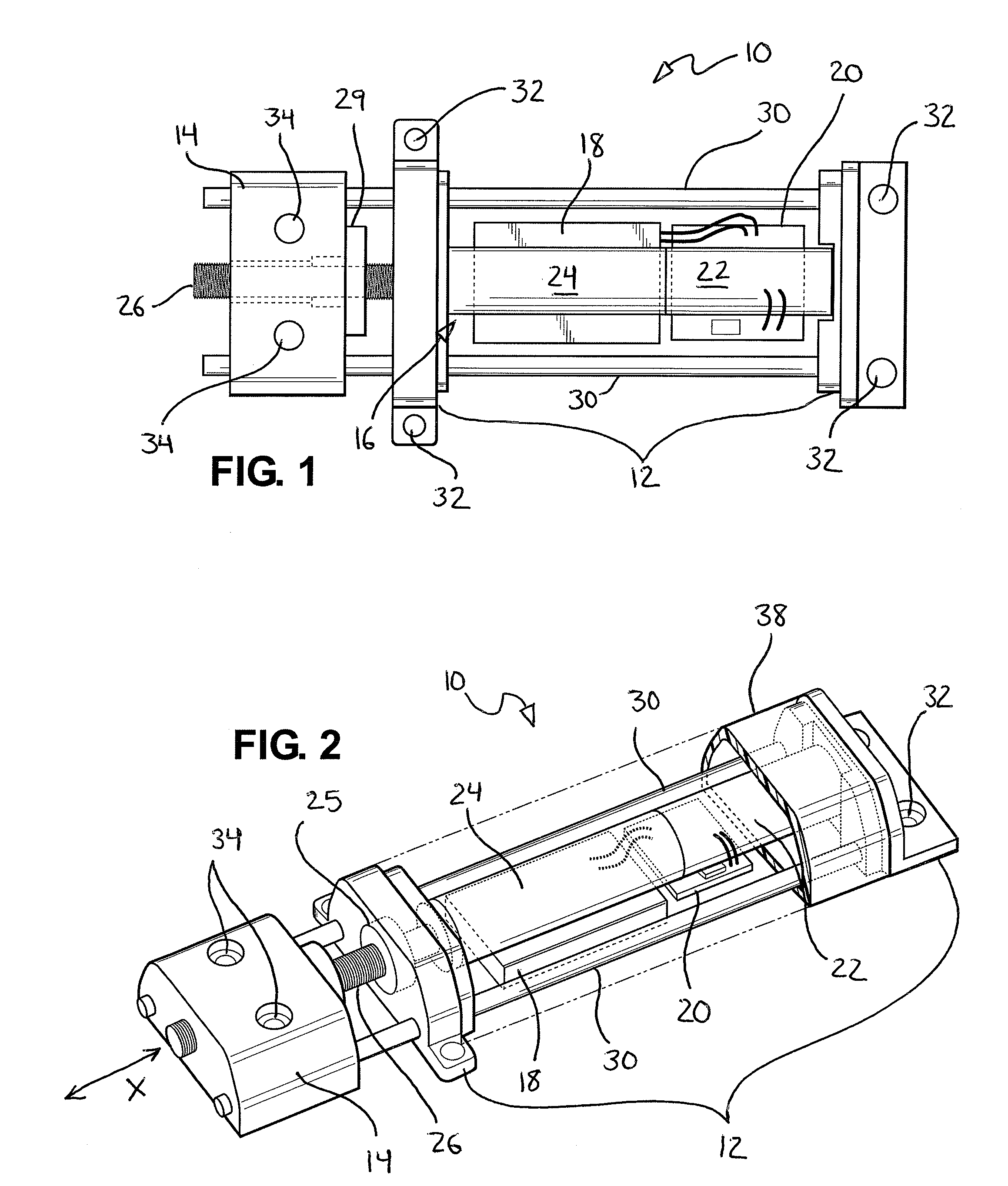
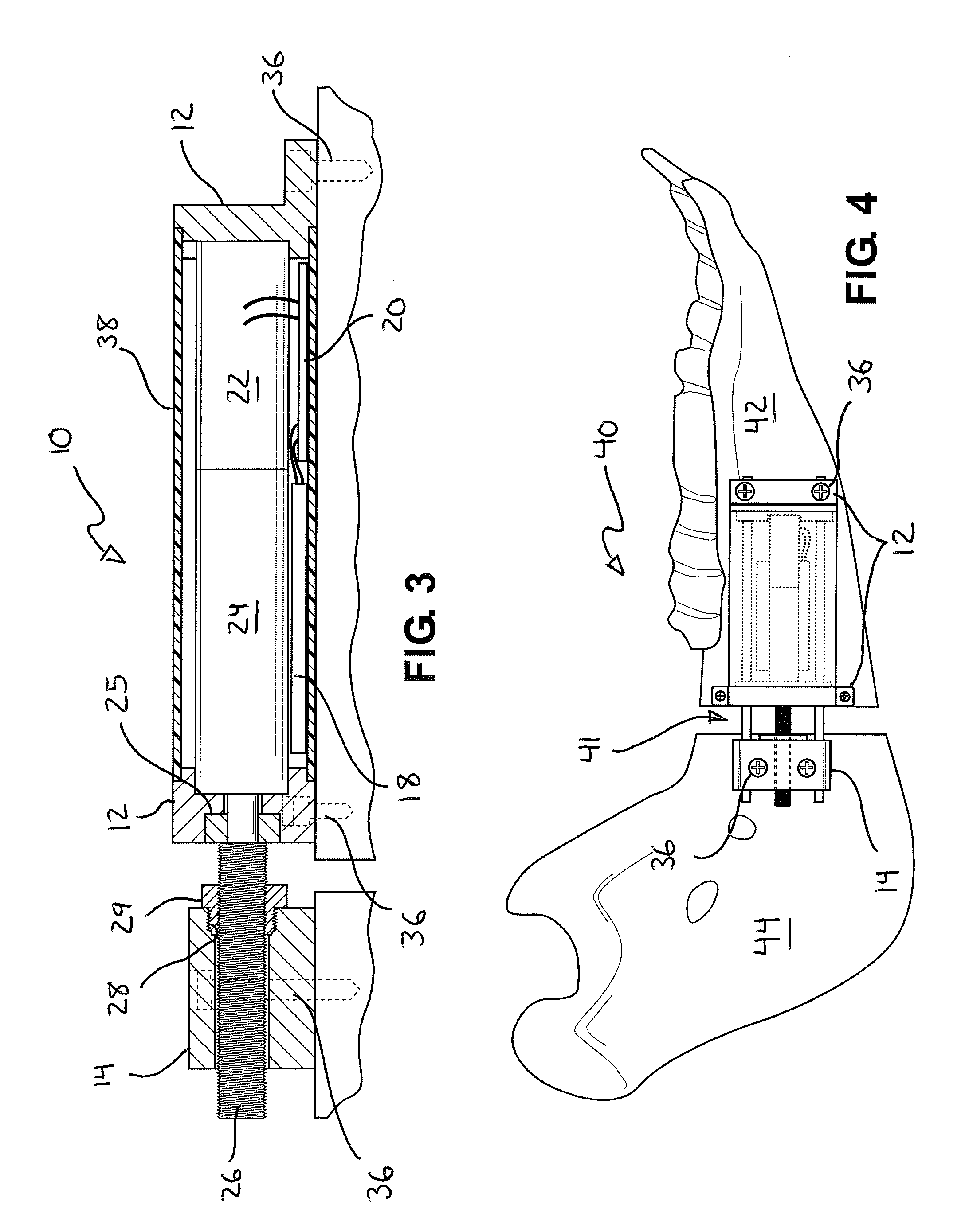
  • Implantable distraction osteogenesis device and methods of using same
  • Implantable distraction osteogenesis device and methods of using same
  • Implantable distraction osteogenesis device and methods of using same

Examples


Embodiment Construction

[0022]As required, detailed embodiments of the present invention are disclosed herein; however, it is to be understood that the disclosed embodiments are merely exemplary of the invention that may be embodied in various and alternative forms. The figures are not necessarily to scale, some features may be exaggerated or minimized to show details of particular components. Therefore, specific structural and functional details disclosed herein are not to be interpreted as limiting, but merely as a representative basis for teaching one skilled in the art to variously employ the present invention.

[0023]Referring to FIGS. 1, 2 and 3, an exemplary implantable osteogensis distraction device 10 for securement to separate bone segments in the body of a patient and operative to generate new bone between said bone segments by the gradual application of a distraction force is shown. The device 10 can be seen to generally comprise attachment members 12, 14 securable to separate bone segments and m...


PUM


Abstract

An osteogenesis distraction device for securement to separate bone segments in the body of a patient and operative to generate new bone between said bone segments by the gradual application of a distraction force, the device comprising attachment members securable to separate bone segments and moveable in relation to each other to generate a distraction force, a power source for powering relative movement of the attachment members, and wherein the entire device, including the attachment members and power source, is dimensioned for implantation entirely subdermally in the body of a patient.

Description

CROSS-REFERENCE TO RELATED APPLICATIONS[0001]This application is related to, and claims the benefit of priority from, U.S. Provisional Patent Application Ser. No. 60 / 978,472, filed Oct. 9, 2007, the disclosure of which application is incorporated herein by reference in its entirety.FIELD OF THE INVENTION[0002]The present invention pertains generally to distraction osteogenesis and, more particularly, to an osteogenesis distraction device comprising attachment members securable to separate bone segments and moveable in relation to each other to generate a distraction force, a power source for powering relative movement of the attachment members, and wherein the entire device, including the attachment members and power source, is dimensioned for implantation entirely subdermally in the body of a patient.BACKGROUND OF THE INVENTION[0003]Distraction osteogenesis is a method of generating new bone in a gap between two bone segments, by the gradual application of tensile stress across the...

Claims


Application Information

Patent Timeline
IPC IPC(8): A61B17/58
CPCA61B17/663A61B17/8004A61B2017/00221A61B2017/00212A61B2017/00022
Inventor FEINBERG, STEPHEN E.SASTRY, ANN MARIECHUNG, MYOUNGDO
Owner RGT UNIV OF MICHIGAN
Learn More