Devices, systems and methods for distraction osteogenesis

a technology of distraction osteogenesis and devices, applied in the field of devices and methods for distraction osteogenesis, can solve the problems that the bone screws placed for anchoring a conventional distraction footplate cannot achieve reasonable stability, and achieve the effects of convenient operation, simple, shorter and more comfortable solutions, and convenient suppor

Active Publication Date: 2021-08-12
OSTEOPHILE LTD
View PDF13 Cites 1 Cited by
  • Summary
  • Abstract
  • Description
  • Claims
  • Application Information

AI Technical Summary

Benefits of technology

[0011]The distraction device is provided with a plurality of string pull assemblies, configured to enable wrapping of each string attached to anchoring implant means during rotation thereof. The wrapping of each string results in a pulling force applied to the osteotomized bone segment via the corresponding anchoring implant means, thereby promoting formation of new bone tissue in the gap formed between the osteotomized bone segment and the remaining basal bone.
[0012]Advantageously, a procedure utilizing the disclosed distraction device reduces the hazard to sensitive regions, such as the inferior alveolar nerve, due to the disclosed distraction device ability to pull small-dimensioned anchoring implant means, such as orthodontic implants, instead of conventional larger bone plates. Moreover, the distraction method disclosed herein enables to perform distraction osteogenesis even in extremely complicated cases, where the amount bone in a region of an alveolar ridge is not suitable for distraction osteogenesis procedures by conventional distractors with bone plates. One such example is the posterior maxilla in which bone screws placed for anchoring a conventional distractor footplate cannot achieve reasonable stability due to thinness of the anterior maxillary sinus cavity.
[0013]A further advantage of the disclosed distraction device, having a plurality of string pull assemblies connected to a corresponding number of anchoring implant means, is that each string pull assembly can be operated independently, thereby applying a different pulling rate or a different distraction length to different regions of an osteotomized bone segment, to which a corresponding anchoring implant means is attached. Thus, applying several points of tension to the osteotomized bone intended for distraction can offer differential bone gain along the surgical region. Moreover, due to the fact the anchoring of the device is superficial and not submerged enables the operator the change the lateral vector of distraction during the distraction phase if the need for a change in the pre-set vector arises. This can be achieved, for example, by disconnecting the distraction device from the dental abutment, adjusting the lateral position of the frame of the distraction device, and reconnecting it back to the abutment.
[0014]A further advantage of the disclosed distraction device, is that it can be easily supported by dental supports known in the art, such as bone screws with or without dental abutments, or even attached to a native tooth. Removal of the distraction device does not require a surgery and can be easily performed, thus providing a simpler, shorter and more comfortable solution, compared with conventional distractors' removal requiring another surgical procedure and the related comorbidities.

Problems solved by technology

Moreover, the distraction method disclosed herein enables to perform distraction osteogenesis even in extremely complicated cases, where the amount bone in a region of an alveolar ridge is not suitable for distraction osteogenesis procedures by conventional distractors with bone plates.
One such example is the posterior maxilla in which bone screws placed for anchoring a conventional distractor footplate cannot achieve reasonable stability due to thinness of the anterior maxillary sinus cavity.

Method used


Image

  • Devices, systems and methods for distraction osteogenesis
  • Devices, systems and methods for distraction osteogenesis
  • Devices, systems and methods for distraction osteogenesis

Examples


Embodiment Construction

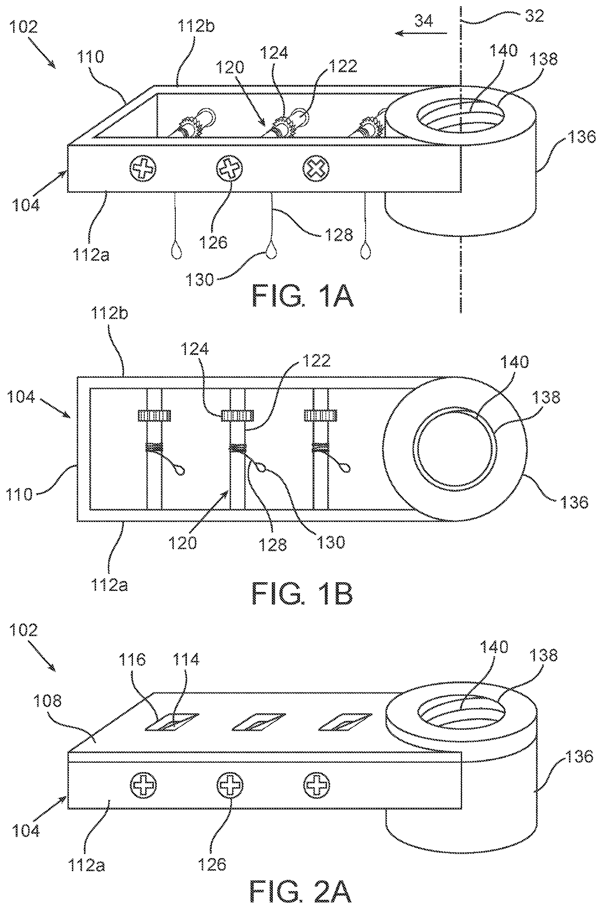
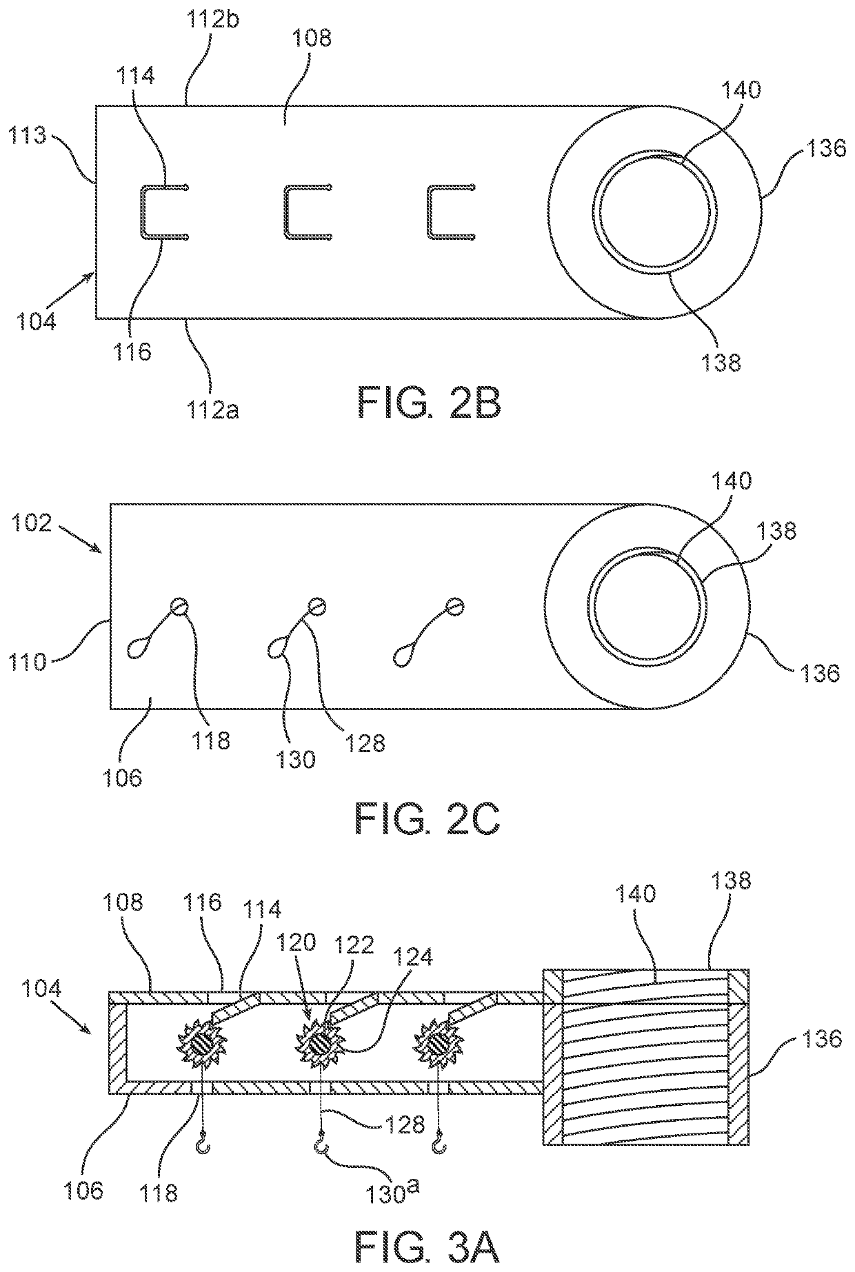
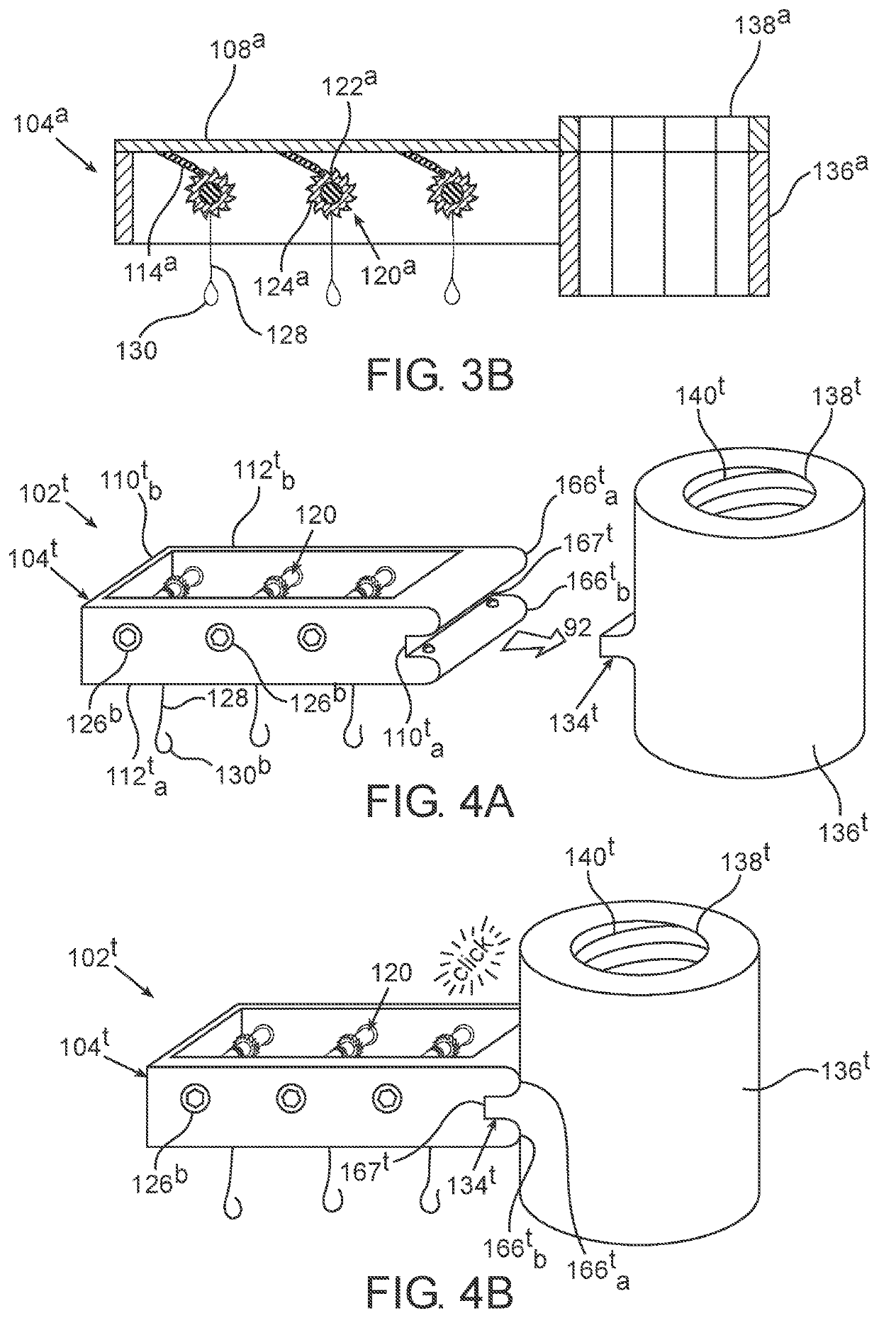
[0185]In the following description, various aspects of the disclosure will be described. For the purpose of explanation, specific configurations and details are set forth in order to provide a thorough understanding of the different aspects of the disclosure. However, it will also be apparent to one skilled in the art that the disclosure may be practiced without specific details being presented herein. Furthermore, well-known features may be omitted or simplified in order not to obscure the disclosure. In the figures, like reference numerals refer to like parts throughout.

[0186]Throughout the figures of the drawings, different superscripts for the same reference numerals are used to denote different embodiments of the same elements. Embodiments of the disclosed devices and systems may include any combination of different embodiments of the same elements. Specifically, any reference to an element without a superscript may refer to any alternative embodiment of the same element denote...


PUM


Abstract

The present invention relates to the field of devices and methods for distraction osteogenesis, and, more particularly, to distraction devices and distraction systems used in the treatment of mandibular or maxillary alveolar ridge atrophy, and to methods for utilizing a distraction device or a distraction system for bone tensioning.

Description

FIELD OF THE INVENTION[0001]The present invention relates to the field of devices and methods for distraction osteogenesis, and, more particularly, to distraction devices and distraction systems used in the treatment of mandibular or maxillary alveolar ridge atrophy, and to methods for utilizing a distraction device or a distraction system for bone lengthening.BACKGROUND OF THE INVENTION[0002]Mandibular or maxillary alveolar ridge atrophy is a known pathology, which can develop as a slow process of volume deterioration after tooth loss or acutely due to an inciting event as infection, cyst removal, traumatic tooth extraction, tumor resection or trauma. Adequate alveolar ridge volume is crucial for placement of dental implants. Placement of dental implants and the long-term prognosis of such primarily depend on the size of the dental implants, the ratio between them and the prosthesis attached to them and their spatial location relative to the intra jaw teeth and opposed jaw occlusio...

Claims


Application Information

Patent Timeline
Patent Type & Authority Applications(United States)
IPC IPC(8): A61B17/66
CPCA61B17/666A61C8/00A61C8/0006A61B17/663A61C3/00
Inventor LAZAROVICI, TOWY
Owner OSTEOPHILE LTD
Why Eureka
Try Eureka