
Transport distraction apparatus

a technology of transport distraction and apparatus, applied in the field of osteogenesis, can solve the problems of significant donor site morbidity, large maxillectomy defect reconstruction after tumour resection, and the inability of most existing maxillofacial transport distractors to be practically suited to distraction

Inactive Publication Date: 2018-01-16
UNIVERSITY OF CAPE TOWN
View PDF29 Cites 2 Cited by
  • Summary
  • Abstract
  • Description
  • Claims
  • Application Information

AI Technical Summary

Benefits of technology

The invention is a transport distraction apparatus for performing transport distraction osteogenesis, which involves using a track, a carriage, and a fixation plate to adjust the position of the fixation plate relative to the track. The track has formations along its edge that allow for the carriage to move along the track in a curved shape. The apparatus also includes a gear for moving the carriage along the track and a titanium material that is deformable to follow a required contour in at least one plane. The track has a plurality of apertures located centrally with respect to its width and can be bent to follow a required contour. The fixation plate is a flat plate with deep sector shaped cut-out portions that can conform to a three-dimensional curve. The fixation plate can be made of titanium or medical grade stainless steel and has multiple perforations for securing it in position. The technical effects of the invention include improved transport and distraction of bone during osteogenesis procedures.

Problems solved by technology

Reconstruction of large maxillectomy defects following tumour resection presents a formidable challenge to both surgeons and prosthodontists.
Due to the large size and complexity of various maxillectomy defects, the structural and functional restoration requires composite tissue replacement involving free vascularized flaps harvested from the tibia or fibula.
These procedures demand long and skillful surgical techniques and, though often highly successful, are not always predictable and cause significant donor site morbidity.
However, most existing maxillofacial transport distractors are not practically suited to distraction in the anterior curved segment of the maxilla.
These devices are uncomfortably large and do not perform well on curvilinear trajectories.
Some distractors are capable of following curvilinear trajectories, but the nature of the designs makes them inappropriate for distraction along curves such as those present in the anterior segments of the mandible and maxilla.
However, it has been found that a two-stage mandibular distraction requires four invasive operations whilst the generated geometry is not true to the ideal form of the mandible.
Due to the complex anatomical constraints of the maxilla, currently available distractors cannot deal with the demands of the upper jaw and at present there are no transport distractors available for anterior to posterior distraction in the maxilla.
However, the device proposed is rather thick in that it requires appreciable space in the direction at right angles to the maxilla or mandible thereby contributing significantly to patient discomfort by protruding and becoming obtrusive inside the patient's mouth.
The device described also has a carriage that is detachable from bracket flanges thereby complicating the mechanism further and making it more bulky.
Considering the anatomical variations and inaccessible spaces of the maxilla, this device besides being cumbersome, is inappropriate to provide traction, especially as the demands may dictate, such as from the right side through the front to the left and to the back of the maxilla.
Also in the maxilla, a three dimensional curvilinear traction may be necessary and the device described may not be able to provide locomotion on a spiral.

Method used


Image

  • Transport distraction apparatus
  • Transport distraction apparatus
  • Transport distraction apparatus

Examples


Embodiment Construction

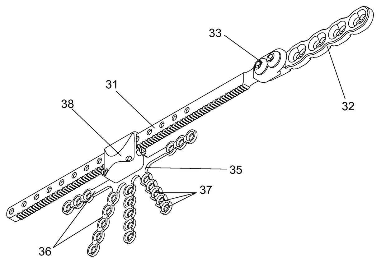
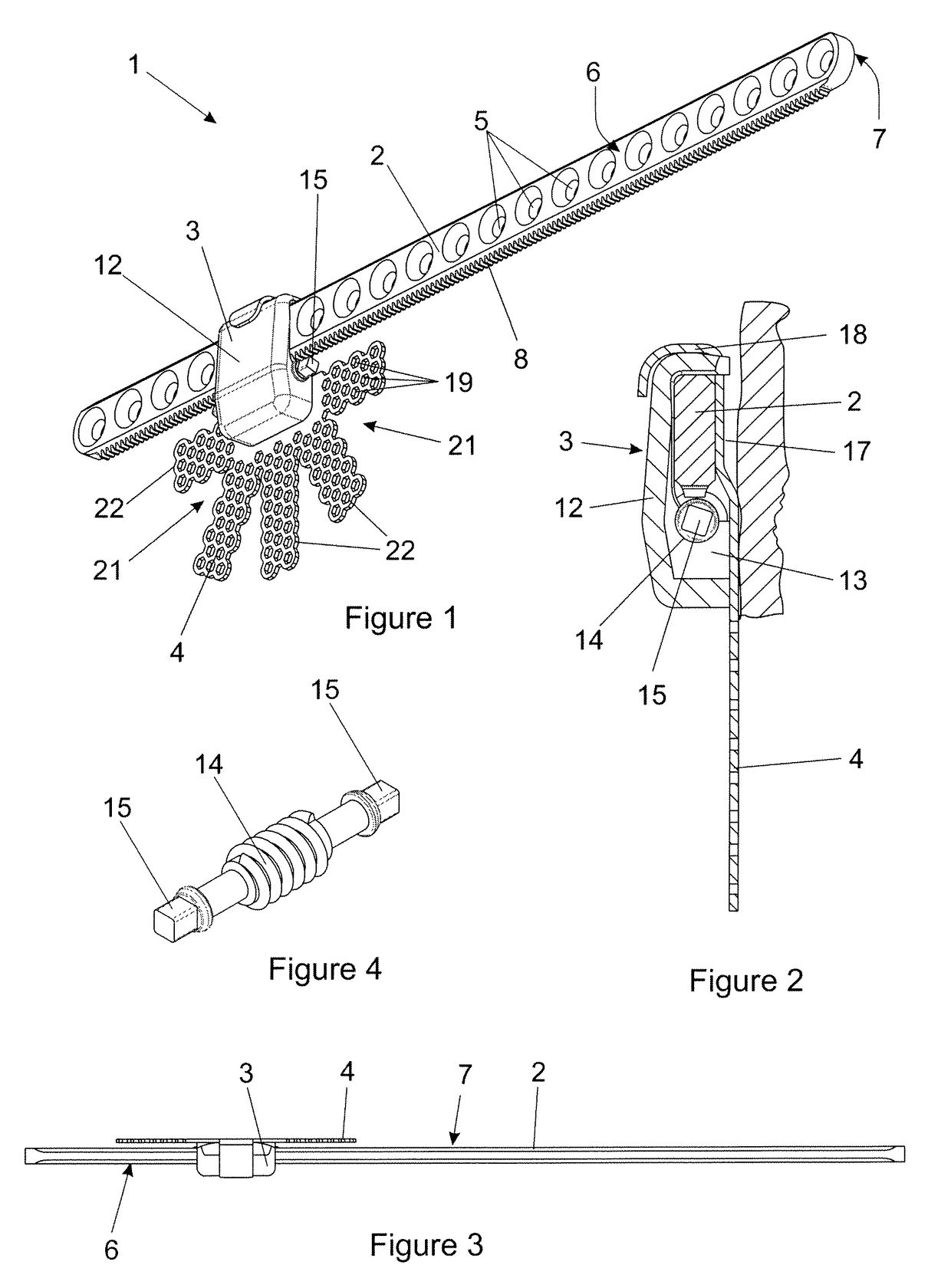
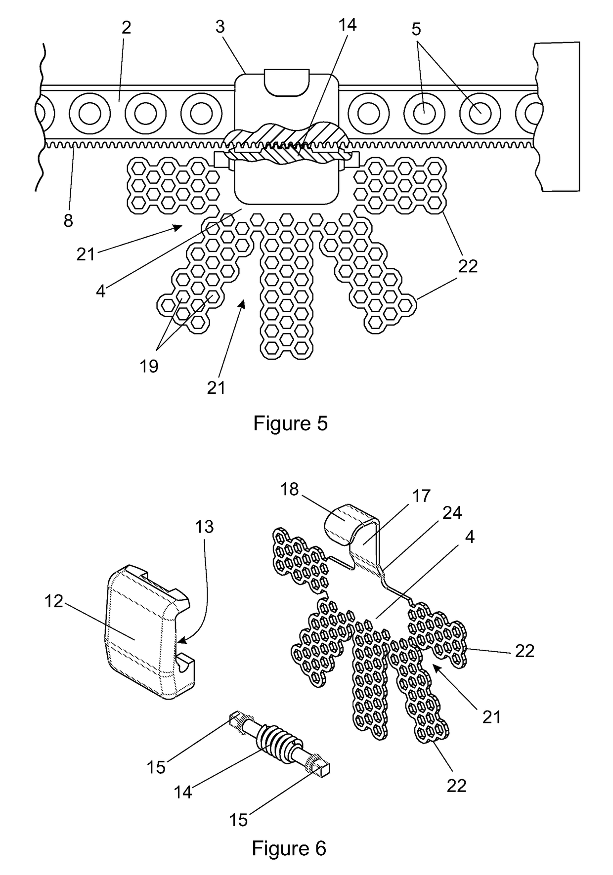
[0038]As illustrated in FIGS. 1 to 7 of the accompanying drawings, one embodiment of transport distraction apparatus (1) according to the invention, hereinafter referred to as “the distractor”, includes a track (2) with a carriage (3) movable along at least a central part of its length wherein the carriage carries a perforated or mesh fixation plate (4). The track (2) is of a type generally known in the art and assumes the form of a titanium strip having a plurality of apertures (5) roughly centrally located with respect to the width of the track and spaced apart along its length. The apertures are suitable for receiving fasteners for securing the track directly to the bone of a patient. The track is such that it may be bent to take on a suitable curvilinear shape in use as shown quite clearly in FIG. 15.

[0039]The width of the track is greater than its thickness to provide a front face (6) and a rear face (7) (see FIGS. 2 and 3) with two longitudinally extending edges. In the presen...


PUM


Abstract

Transport distraction apparatus for performing transport distraction osteogenesis is provided which includes a track capable of being formed into a curvilinear shape with a carriage movable longitudinally along the track. The carriage has a fixation plate secured or securable to it and at least one gear for moving the carriage along the track in order to adjust its position relative to the length of the track. The track has a series of formations extending along one edge of the track and engaged by the gear which is at least partially accommodated within a space between a plane including the front face of the track and a plane including the rear face of the track. Preferably, the apparatus creates a gap between a central region of the track and a patient's bone in use. A fixation plate is also provided.

Description

FIELD OF THE INVENTION[0001]This invention relates to apparatus for use in transport distraction osteogenesis, more particularly, but not exclusively, to osteogenesis for the reconstruction of the human maxilla.BACKGROUND TO THE INVENTION[0002]Transport distraction osteogenesis (TDO) was pioneered at the turn of the 20th century. It was originally applied as a method of leg lengthening to correct discrepancies between legs. As such, its early development was in the area of orthopaedics. The concepts have since been adapted to maxillofacial reconstructive surgery. Transport distraction osteogenesis is now commonly applied to regeneration of the maxilla and mandible where they are absent as well as the correction of various facial bone abnormalities.[0003]Transport distraction osteogenesis involves surgical fracture of the bone, a latent period to facilitate initial healing of the fracture, and then incremental, relative distraction of the fracture surfaces. The relative displacement ...

Claims


Application Information

Patent Timeline
Patent Type & Authority Patents(United States)
IPC IPC(8): A61B17/66
CPCA61B17/663
Inventor VICATOS, GEORGEHENDRIKS, MOGAMAT RUSHDIEBOONZAIER, JAMES ANGUS
Owner UNIVERSITY OF CAPE TOWN
Learn More