
Position marking device for slot hangers

a technology of positioning marking and slot hanger, which is applied in the field of positioning marking device for slot hanger, can solve the problems of time-consuming and frustrating process of hanging a picture frame, mirror, curtain frame, or other objects on the wall in the proper desired position, and the method is highly imprecis

Inactive Publication Date: 2009-08-06
MEGAHED AMR
View PDF8 Cites 41 Cited by
  • Summary
  • Abstract
  • Description
  • Claims
  • Application Information

AI Technical Summary

Benefits of technology

[0006]It is an object of the present invention to provide a relatively simple apparatus and method for locating nails, hooks, or other fasteners used to support a picture frame, mirror, or other object on a wall.
[0009]Still anther object is to provide a marking device for use in the method of the invention that is simple and economical in construction and reliable in usage.

Problems solved by technology

Hanging a picture frame, mirror, curtain frame, or other objects on a wall in a proper desired position can be a time consuming and frustrating process.
The method is highly imprecise, can be very awkward to carry out, and usually, the mark is only the approximate location of where the hanger should be placed.
Such method has the additional disadvantage in that it makes disfiguring marks on the wall, often at locations far removed from the actual required hanger site.
When larger items are to be hung which have two or more key hole slot hangers or the like, the task becomes even more cumbersome, requiring the installer to measure the distance between the slots.
The method requires considerable guess work and proves to be inaccurate in achieving a perfectly balanced finally hung product.
While a number of approaches have been proposed for locating the position of fastening nails or other hangers on the wall, these approaches also often have been cumbersome to carry out, required adhesives, strings, wires, or the like, or were not easily useable with key hole or other slotted hanger hardware.
Such prior fastener locating devices also can be complicated and expensive for purchase for relatively infrequent household usage.

Method used


Image

  • Position marking device for slot hangers
  • Position marking device for slot hangers
  • Position marking device for slot hangers

Examples


Embodiment Construction

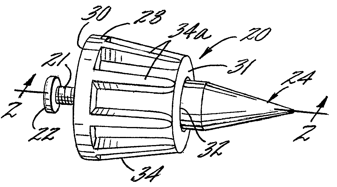
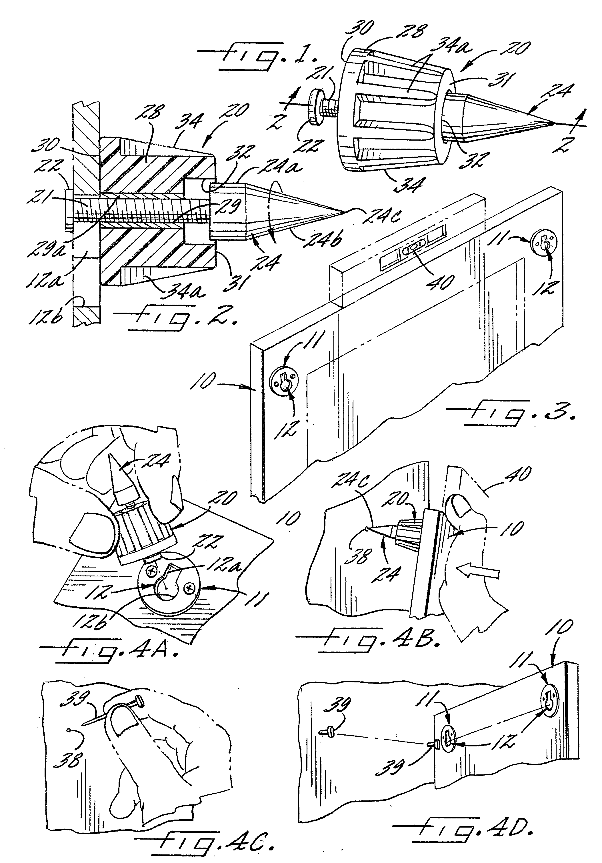
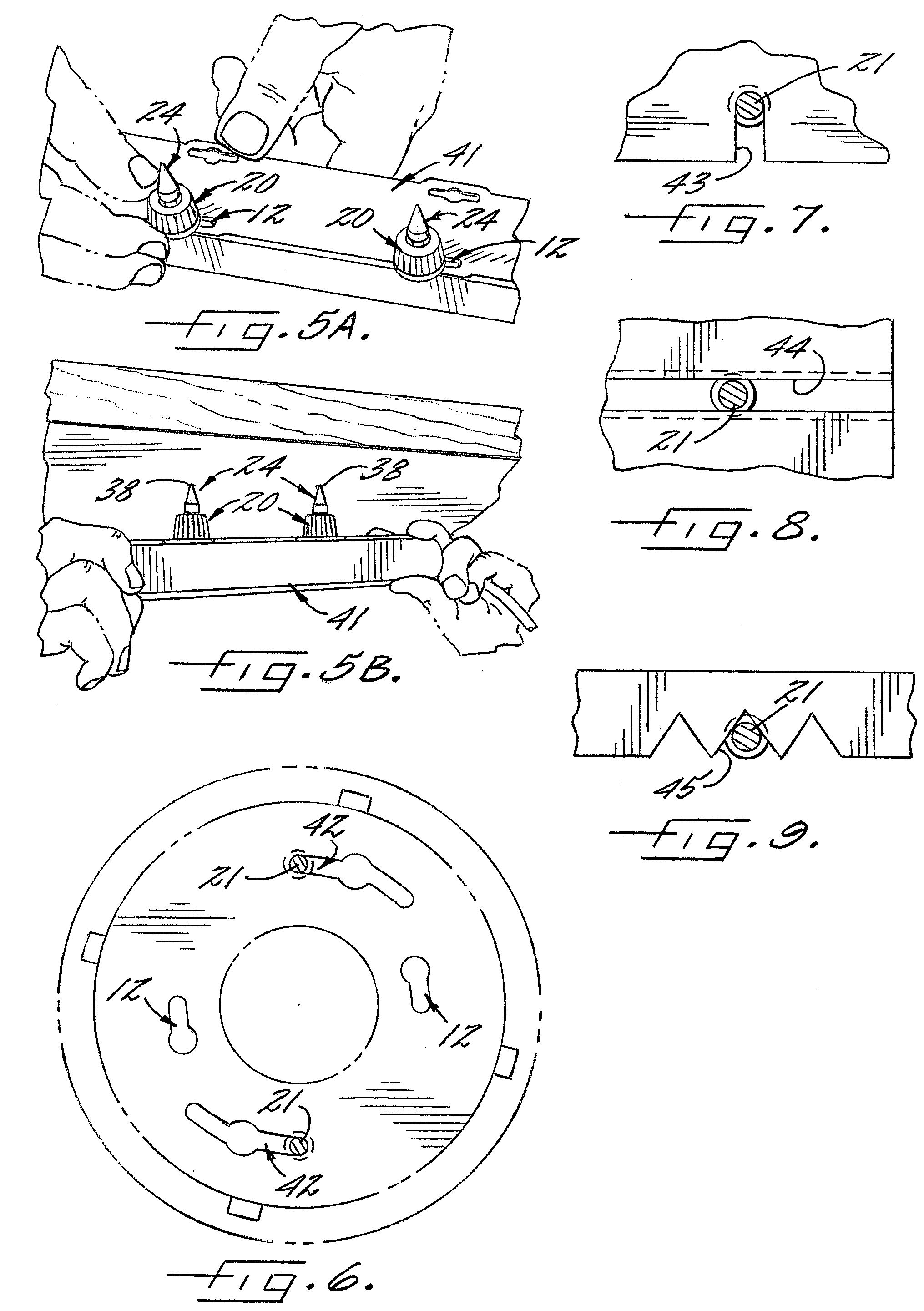
[0019]Referring now more particularly to the drawings, there is shown an illustrative frame 10 having a plurality of mounting plates 11 fixed on a rear side thereof. Each mounting plate 11 in this case is formed with a key hole mounting slot 12, having a relatively narrow width, vertically extending upper slot section 12a communicating with a relatively larger diameter, rounded bottom opening 12b. As understood by persons skilled in the art, such key hole slots 12 are adapted to receive the head or protruding end of a nail, screw, hook or like fastener secured in the wall, with the head or end of the fastener being positioned through the enlarged diameter rounded bottom section portion 12b, and with the smaller width slot section then being lowered down on to the shaft or stem of the fastener.

[0020]In accordance with the invention, a relatively simple marking device is provided that can be positively, but releasably secured, within a respective mounting slot of the object to be wall...


PUM


Abstract

A method of hanging an object on a wall with a marking device having a threaded shaft, an enlarged diameter head fixed at one end of the shaft, a pointed marking end fixed at an opposite end of the shaft, and a threaded nut mounted on the shaft for axial movement. The shaft of the marking device is positionable into the slot of the item to be hung, and is fixed therein by the nut. Upon positioning of the object and the marking device fixed thereto into desired mounted position on the wall, application of an axial force to the shaft of the marking device will cause a pointed end thereof to create a mark for insulation of a nail or other fastener in the wall at the point of the mark.

Description

CROSS-REFERENCE TO RELATED APPLICATIONS[0001]This patent application claims the benefit of U.S. Provisional Patent Application No. 61 / 026,329, filed Feb. 5, 2008, which is incorporated by reference.FIELD OF THE INVENTION[0002]The present invention relates generally to an apparatus and method for locating a nail, hook, or other fastener used for hanging or securing a picture frame, mirror, or other object on a wall, and more particularly, to an apparatus and method effective for marking the wall at the proper site for the hanging the object by means of a key hole slot or hanging hardware slot-like opening provided on a rear side of the object to be hung.BACKGROUND OF THE INVENTION[0003]Hanging a picture frame, mirror, curtain frame, or other objects on a wall in a proper desired position can be a time consuming and frustrating process. It is common for persons wishing to hang a picture frame, for example, to hold the frame in the desired mounted position, and attempt with a finger, p...

Claims


Application Information

Patent Timeline
IPC IPC(8): B25H7/04
CPCB25H7/04A47G1/205
Inventor MEGAHED, AMR
Owner MEGAHED AMR
Learn More