External fixation apparatus and method

a bone pin and apparatus technology, applied in the field of external bone pin fixation apparatus and method, can solve the problems of reducing the user's ability to sense or feel the level, difficult for the user to manipulate the arch into proper position and control the apparatus, and user's very little feel or sensory input, so as to simplify the apparatus and less unwieldy use

Inactive Publication Date: 2005-03-01
PIONEER SURGICAL TECH INC
View PDF57 Cites 77 Cited by
  • Summary
  • Abstract
  • Description
  • Claims
  • Application Information

AI Technical Summary

Benefits of technology

In accordance with the present invention, a bone fixation apparatus and method are provided that substantially integrates the mechanism for advancing a non-invasive pin to an external pin positioner so as to simplify the apparatus and make the entire apparatus less unwieldily to use. More particularly, the positioner has a pin holder which includes a pin advance assembly integrated therewith. In this manner, the present fixation apparatus avoids the use of an applicator gun or the like so that the positioner is directly gripped by the user for orienting the pins in position for being advanced into engagement with the bone.
In another form of the invention, the fixation apparatus includes a pair of pin positioners having arcuately configured bodies. An adjustable connection is provided between the bodies to allow the pins supported thereby to be angularly shifted about a bone for obtaining different angles of pin-to-bone orientation. This provides the bone fixation apparatus with significant flexiblity in terms of where the pins engage the bone so as to allow pin orientations that cause the minimum amount of interference with surrounding nerves, blood vessels, muscles and the like. To this end, it is preferred that pin holders in the form of modules carrying one or multiple bone pins be releasably connected to one of the ends of each of the positioner bodies. With the modular form, a user can interchange the modules on the positioner bodies depending on the number of bone pins needed at the angle of orientation selected for the bone pin or pins for the bone surface to be engaged thereby.

Problems solved by technology

One problem noted with these generally non-invasive fixation devices is the use of high-force actuators or applicators such as by levers and the like that reduce the user's ability to sense or feel the level of force with which the pins are brought into engagement with the bones and the position at which the pin is engaged with the bone.
This arrangement with the arch cantilevered off the front end of the gun makes it difficult for the user to manipulate the arch into proper position and to control the apparatus during the application process due to the heavy front-loaded weight of the entire apparatus.
Further, the user has very little feel or sensory input as to whether there was good anatomical placement of the pin on the bone and the level of force with which the pin was engaged with the bone.
As the applicator pistol is not designed to stay with the fixator arch and pins gripped on the bone during healing, further complexities are necessarily added to the Ballier apparatus by the releasable latching mechanism provided between the gun and the arch.
Thus, increasing the separation between the balls entails a corresponding increase in the size of the clamping plate creating extra weight for the apparatus.
Extra weight is undesirable from both an application standpoint as earlier considered, as well as from a patient's perspective who will usually have to wear the device for several days during the bone-healing process.
The problem with the small separation of the connecting rods is that the rod connected fixators tend to lack stability as they approach a coplanar relation with the bone axis.
In other words, the closer the rods are together, the less stable the whole bone fixation system becomes; similarly, as the angular spacing of the connecting rods approaches 180 degrees, and thus again approximating a coplanar relation with each other, stability in directions transverse to the planes between the rods and bone is lost.
With the current Ballier fixators having the above-described small separation and the relatively small angular spacing therebetween, the overall fixation system lacks the rigidity and stability that is desired.

Method used


Image

  • External fixation apparatus and method
  • External fixation apparatus and method
  • External fixation apparatus and method

Examples


Embodiment Construction

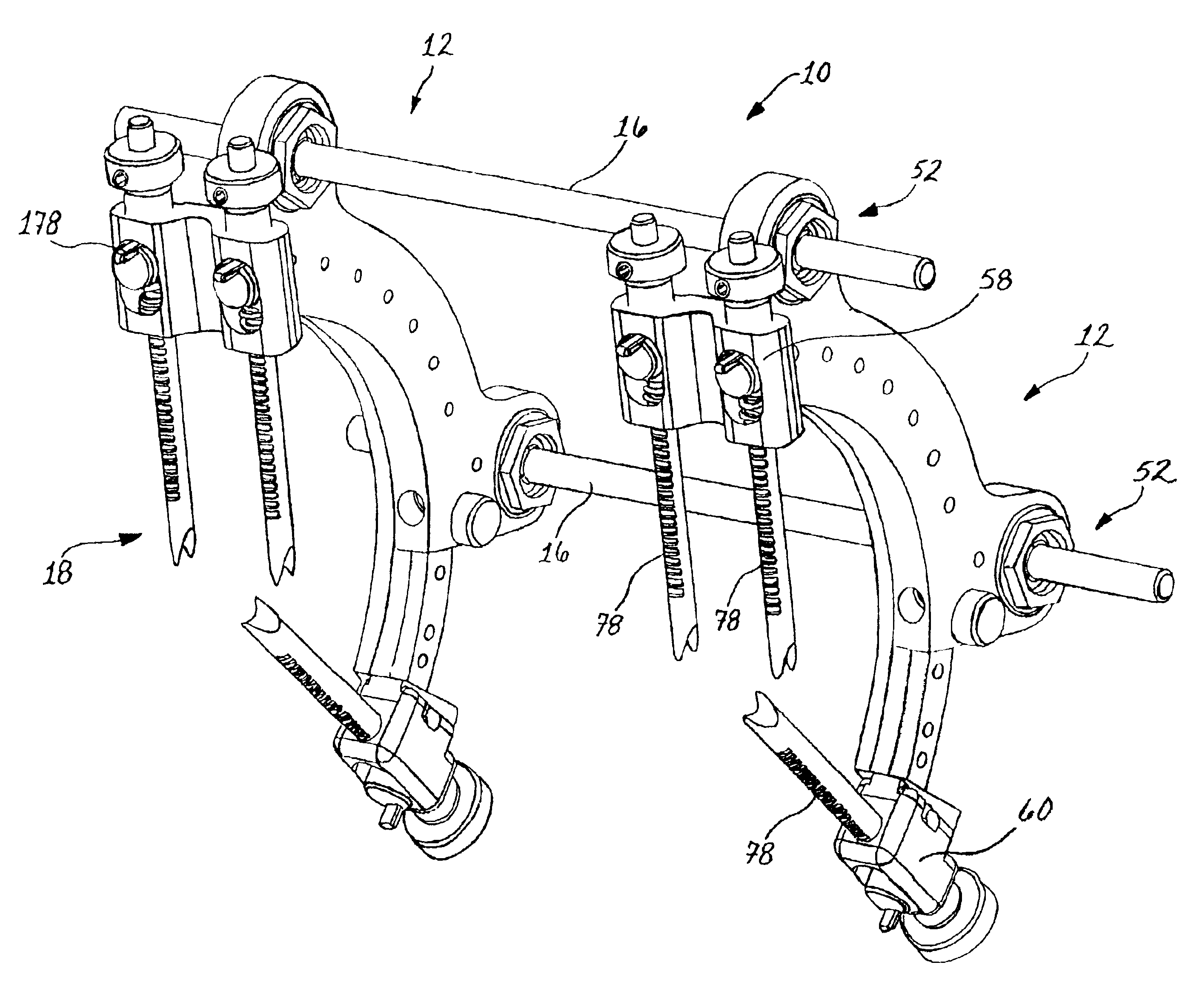
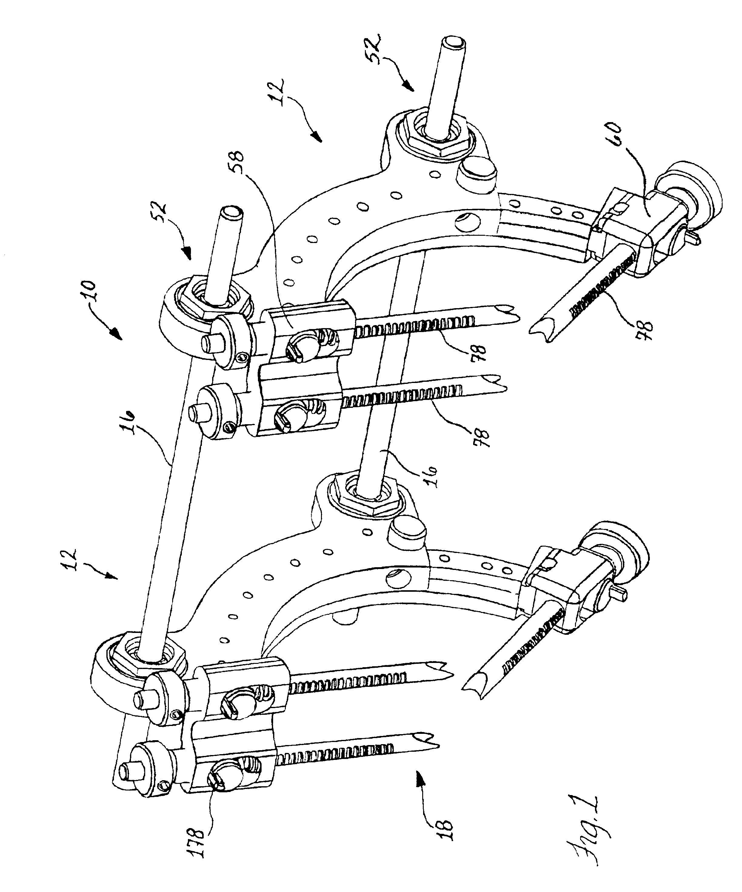
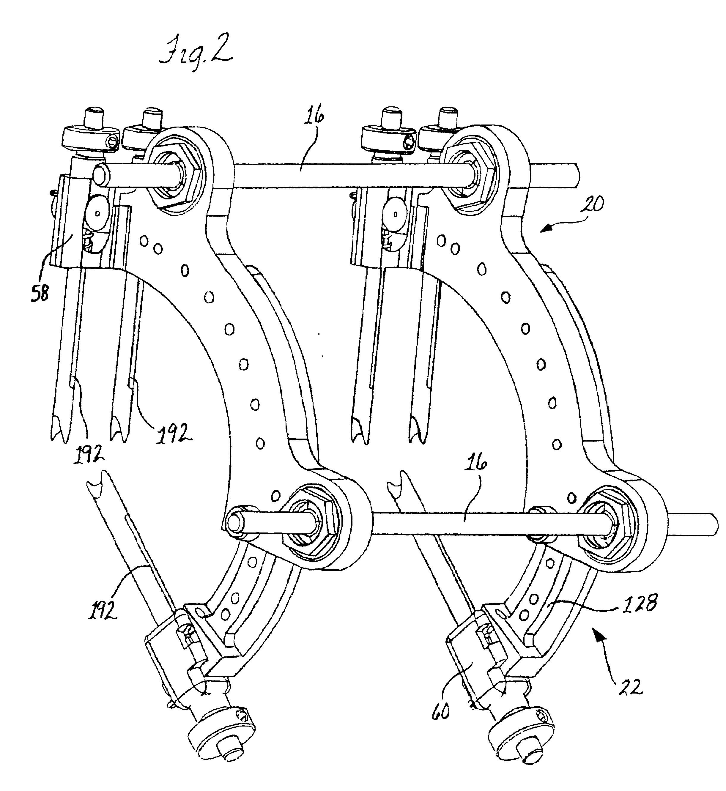
In FIGS. 1 and 2, a bone fixation system generally designated 10 is depicted in its preferred form having bone fixators 12 for being pinned to a bone such as the tibia 14 with the fixators 12 interconnected by rods 16. The present system 10 including the fixators 12 is improved in several respects over prior external bone fixation systems. These improvements relate to the ease with which the bone pins 18 are applied to the bone 14 and the ability of the user to accurately sense proper anatomical placement of the pins 18 on the bone 14 and the level of force with which the pins 18 are engaged therewith.

Further improvements relate to other ergonomic aspects such as the size of the fixators 12 which keeps the user applying the pins 18 close to the application site again making proper application of the pins 18 easier and making the device more comfortable to wear over sustained periods of several days, as will commonly be the case with tibia fractures and the like. To this end, the pre...


PUM


Abstract

A bone fixation apparatus and method are provided that allow a user to push bone pins into engagement with bones with more precision and accurate feel as to proper engagement and the clamping forces between the pins and bone over prior devices utilizing applicator guns and the like. Fine tuning of the clamping forces is also contemplated. Compact and highly ergonomic bone fixators are provided which allow the user to remain close to the pin application site during clamping of the pins onto the bone. Significant flexiblity is preferably incorporated by having two adjustably connected positioner bodies which can each mount a pin holder module releasably attached thereto. A fixation system with improved rigidity is also provided by way of independent clamping members for each of a pair of rod mounts on each pin positioner. The independent clamp members keeps their size to a minimum while allowing the angular separation of connecting rods secured in the rod mounts and spanning and interconnecting two fixators to be optimized, e.g. approximately eighty degree angular spacing, from a system stability standpoint.

Description

FIELD OF THE INVENTIONThe invention relates to an apparatus and method for fixing bone pins to a bone from external of a patients body and, more specifically, to external bone fixation systems including bone fixators secured along a bone and rigidly connected to each other.BACKGROUND OF THE INVENTIONIt is known to use external bone fixators to reduce fractures in bones such as with fractures of the tibia. Advances in fixators have been made in terms of avoiding the infections that can be caused by use of bone pins that penetrate beyond the bone cortex such as into the tibial canal, or completely through the bone. In these devices, the bone pins typically have a distal bone engaging end having a split prong configuration for tight gripping of the bone surface. Herein, the term non-invasive pins means that the pins do not penetrate the bone canal or the cancellous bone material. Accordingly, when these bone pins are applied in their intended manner they substantially obviate the conce...

Claims


Application Information

Patent Timeline
Patent Type & Authority Patents(United States)
IPC IPC(8): A61B17/64A61B17/60
CPCA61B17/645A61B17/6416A61B17/6466
Inventor JANOWSKI, BRIAN P.TRUDEAU, JEFFREY L.
Owner PIONEER SURGICAL TECH INC
Why Eureka
Try Eureka