Dual mode luminous ball pen

a technology of luminous ball pen and luminous ball pen, which is applied in the field of luminous pen, can solve the problems of unintentional touch, power consumption, and continuous turning of leds, and achieve the effect of effectively avoiding unnecessary power consumption

Inactive Publication Date: 2009-08-06
SPARK GOLD
View PDF5 Cites 12 Cited by
  • Summary
  • Abstract
  • Description
  • Claims
  • Application Information

AI Technical Summary

Benefits of technology

[0014]According to another aspect of the present invention, the tapered transparent tip portion (2) may be rotated to switch the power on / off to turn on / off the lamp (5). When the lamp (5) is turned off, regardless of how many times the button is pressed, the LEDs (55a, 55b) will not be turned on or even when users accidentally touch the button, the LEDs (55a, 55b) will not be turned on and thus the unnecessary power consumption may be effectively avoided.

Problems solved by technology

1. Press button on top of the pen shaft usually must be pressed downward several times to activate LED. For example, to light up LED once, the press button must be pressed downward, at least three times in order to light up LED and vice versa, impel pen nib from a retract position to a written position and vice versa. When two LEDs are disposed in a pen shaft, the press button must be pressed six times to determine light / dim modes of two LEDs, and retract / written positions of pen nib. In other words, one LED may be lit up one time, as the press button is pressed into the top end of pen shaft up to six times. Therefore, how to reduce the number of pressing times of a button is an important issue for improving the convenience of usage of the luminous pen.
2. When a luminous ball pen is not in use, users may unintentionally touch the press button, or rotate the upper or lower shaft, or click the key bulged out from the shaft. As a result, LEDs are being continuously turned on and consume power. Therefore, how to prevent such unintentional turning on of the LEDs is another important issue prevent unnecessary wastage of power.
3. Dual mode luminous ball pen may provide a first LED on top of the pen shaft to illuminate surrounding environment, but no projected images can be presented by the first LED. Therefore, how to increase a projected image function of the first LED is yet another important issue to improve the esthetic appearance of the luminous pen.

Method used


Image

  • Dual mode luminous ball pen
  • Dual mode luminous ball pen
  • Dual mode luminous ball pen

Examples


Embodiment Construction

[0032]The description is described in detail according to the appended drawings hereinafter.

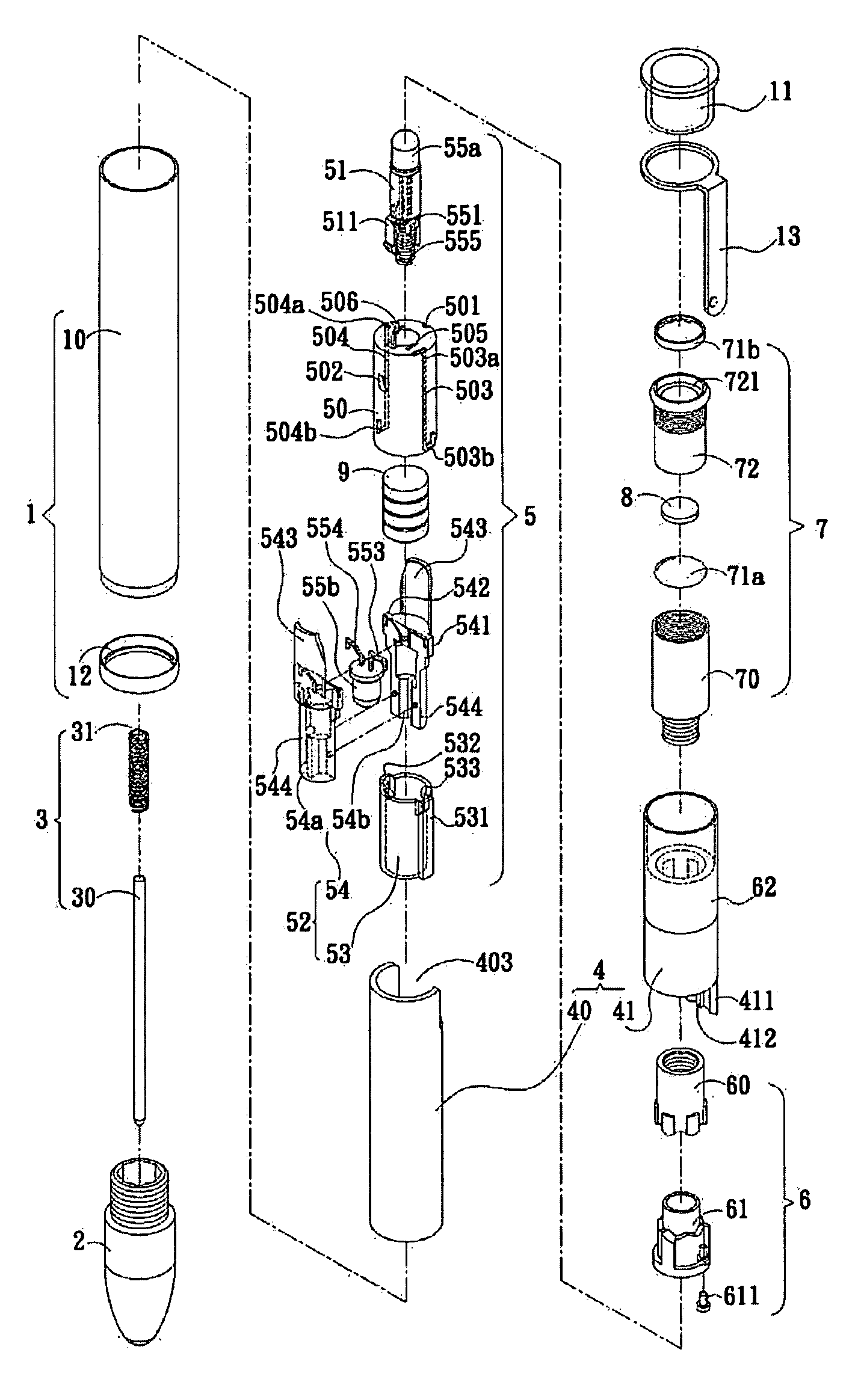
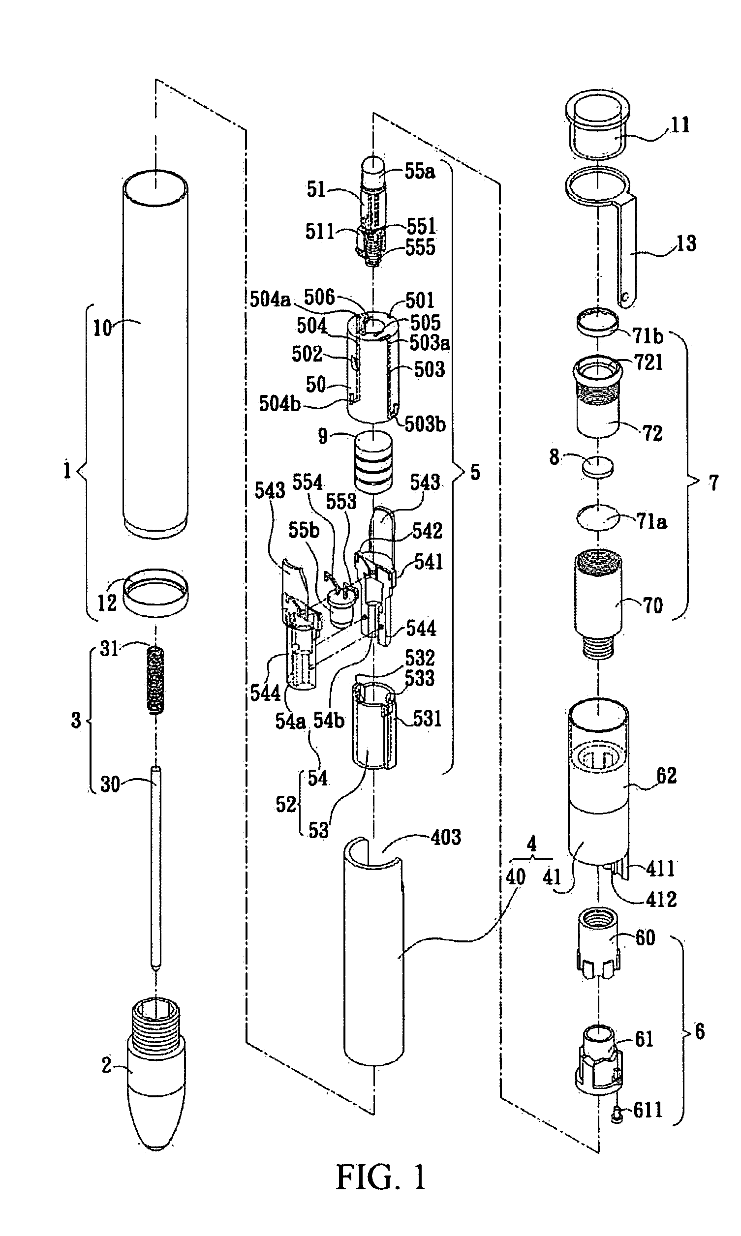
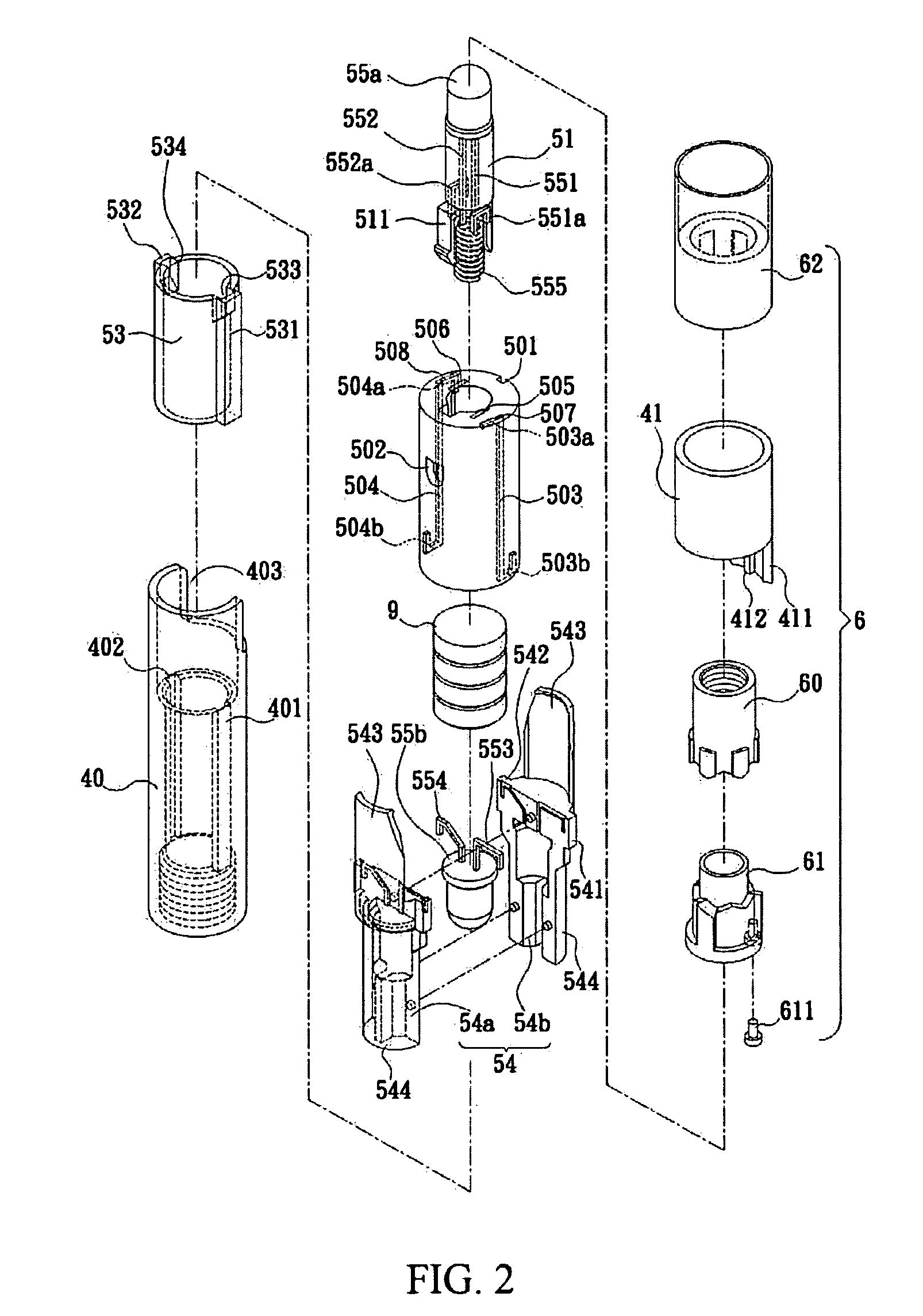
[0033]As shown in FIGS. 1˜4, a dual mode luminous pen includes a shaft 1, a tapered transparent tip portion 2, a refill 3, a switch portion 4, a lamp 5 having at least a cell 9, a control portion 6, and a button 7.

[0034]The shaft 1 is a hollow tube. The tip portion 2 is disposed to a proximal end of the shaft 1. The tip portion 2 is made of, for example, acrylic or the like, which is pervious to light. Rather, the tip portion 2 can be rotated by hand by manual operation. The refill 3 is configured by a specific refill 30 urged by an expansion spring 31 to retract or advance the refill 30 in use through the tip portion 2 where a nib of the refill is retracted into the tip portion in a retracted position, or advanced forward out of the tip portion in a written position. Ink contained in the refill 30 flows to nib for a writing purpose. The switch portion 4 is disposed inside the shaft 1 is conn...


PUM


Abstract

A dual mode luminous ball pen is disclosed. The luminous pen includes a pen shaft; a tapered transparent tip portion disposed on a proximal end of the shaft; a refill, a switch portion, a lamp, a control portion, and a button. The switch portion disposed inside the pen shaft and connected to the tip portion for rotating a sleeve. The lamp includes at least a cell, a first light emitting diode (LED), and a second LED, and can be rotated together by the sleeve to supply/cut-off a power supplied by the cell to the LEDs. The control portion is disposed on the switch portion to turn on one of the first and second LEDs. The button is depressed into the pen shaft to rotate the control portion.

Description

BACKGROUND OF THE INVENTION[0001]1. Field of the Invention[0002]The present invention is related to a luminous pen with a pair of light emitting diodes under dual mode control.[0003]2. Description of Related Art[0004]We are already familiar with Luminous ball pen, and a variety of patented luminous pens are described in domestic and foreign patent documents. In summary, light emitting diode (LED) is disposed on a top end of the pen shaft emits light for illuminating surrounding environment or for making the pen look interesting and attractive. LED disposed may be disposed near a pen tip portion such it emits light while writing so that when writing in the dark, the surrounding environment is illuminated. Alternatively, the LED may be disposed at a middle portion of the pen shaft to emit light for illuminating the trademark or patterns formed thereon.[0005]Most LEDs switches on or off by pressing buttons on the top end of pen shaft, or LEDs may be turned on or off by rotating upper o...

Claims


Application Information

Patent Timeline
Patent Type & Authority Applications(United States)
IPC IPC(8): B43K29/10
CPCB43K24/084B43K29/003G03B29/00B43K29/10G03B21/00B43K29/007Y10S362/80
Inventor LIU, YU-YIN
Owner SPARK GOLD
Why Eureka
Try Eureka