Strut joint for an external fixator

a technology of fixator and strut, which is applied in the field of ball joint for a rod, can solve the problem of inconvenient use of said devices

Active Publication Date: 2009-08-06
STRYKER EURO OPERATIONS HLDG LLC
View PDF43 Cites 42 Cited by
  • Summary
  • Abstract
  • Description
  • Claims
  • Application Information

AI Technical Summary

Benefits of technology

[0010]It is an advantage of the present invention to allow the tightening step of both functions to be executed with one movement. For a complete loosening of the device usually two operations are necessary due to the self locking property of the hole fixation.
to allow the tightening step of both functions to be executed with one movement. For a complete loosening of the device usually two operations are necessary due to the self locking property of the hole fixation.

Problems solved by technology

The use of said devices is inconvenient since the two rings, between which the struts are to be arranged, need to be in nearly perfect orientation to fit the straight rods through the ring holes of said rings.

Method used


Image

  • Strut joint for an external fixator
  • Strut joint for an external fixator
  • Strut joint for an external fixator

Examples


Embodiment Construction

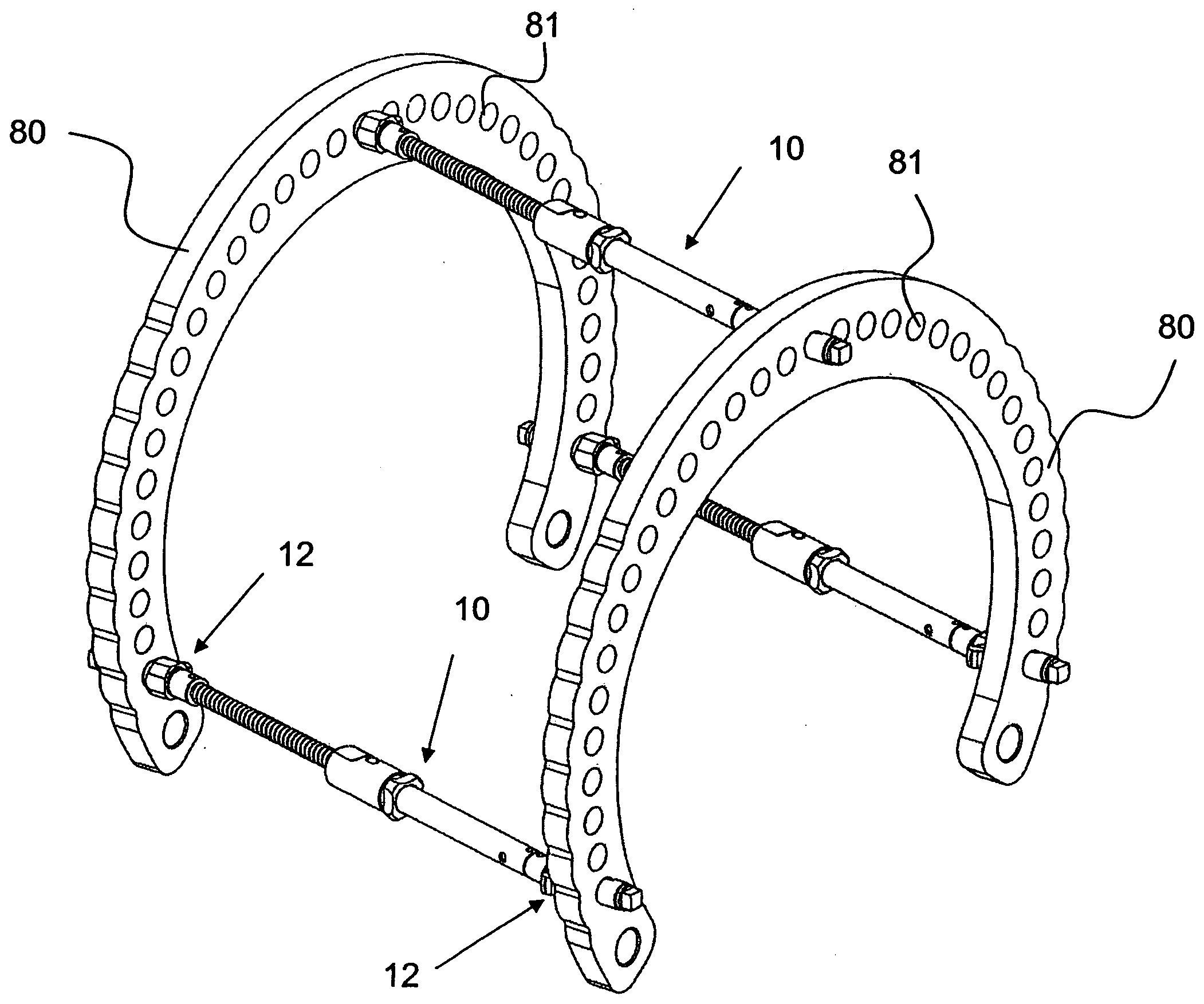
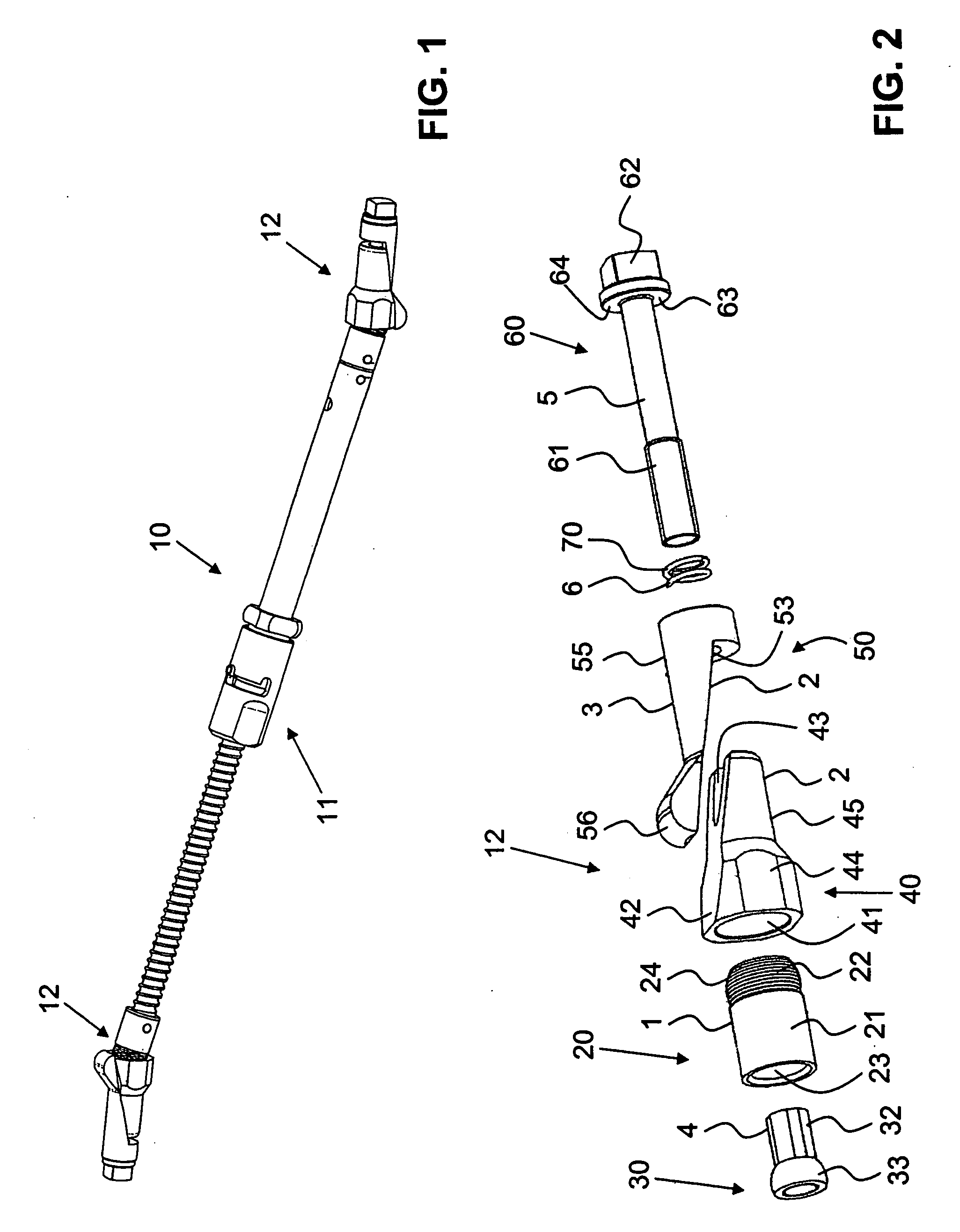
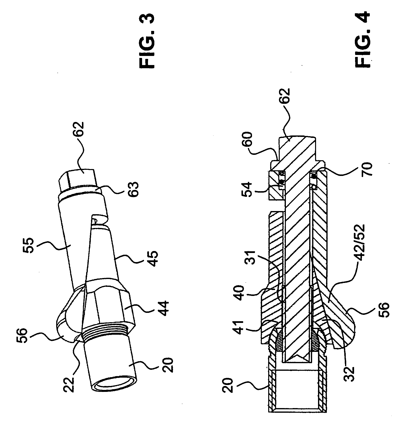
[0018]FIG. 1 shows a perspective view of a strut 10 comprising a rod 11 and two ball joints 12, according to an embodiment of the invention. The strut 10 comprises usually a plurality of single elements, as can be seen for the ball joint in FIG. 2. Preferably, the strut 10 comprises three units, rod 11 and two joints 12, which are usually connected either with an element of the rod 11 being also part of a corresponding joint 12 or wherein the joint is connected with a screw or bayonet connection with the rod 11. FIG. 4 shows an inner rod connection thread 27.

[0019]FIG. 2 shows a perspective view of a ball joint 12 according to an embodiment of the invention. As mentioned above the ball joint 12 comprises a sleeve 20 being connected to a rod 11 of the strut 10 in a predetermined way. This can be done in many ways known to the person skilled in the art. Sleeve 20 of FIG. 2 therefore comprises a cylindrical portion 21 which can be part of the rod 11 or is connected thereto at its free ...


PUM


Abstract

A ball joint for use with an external fixator has a sleeve in engagement with a rod of a strut for the external fixator. A ring insert and a blocking element are provided, having a combined circumferential surface being able to be introduced into a hole of a ring of an external fixator. The ring insert and blocking element have complementary wedge surfaces allowing a relative radial displacement therebetween to enlarge the diameter of the combined circumferential surface for blocking the ball joint inside the hole. Additionally the sleeve comprises a spherical hollow ball portion with concentrical inner and outer spherical portions, wherein the outer spherical portion engages a complementary spherical socket of the blocking element and wherein the inner spherical portion is engaged by a ball nut. A connection element extends through the sleeve, blocking element and ring insert, wherein a radial displacement and axial displacement of the ring insert and blocking element are activated by the connection element.

Description

BACKGROUND OF THE INVENTION[0001]The invention relates to a ball joint for a rod, especially a telescopic rod for an external fixator, especially for use with an external ring fixator. It is further related to a strut comprising a rod and two ball or universal joints at the free ends of the rod.[0002]A plurality of compression-distraction apparatus have been designed and improved by Ilizarov and his group using two external rings to be placed around the limb to be fixed. There are usually at least two such rings, one proximal and one distal ring, which are connected with a plurality of struts or rods. Preferably, these struts are linked to the rings in a way that the attachment points can be pivoted and the length of the strut can be varied to enable adjustment of the external fixation rings.[0003]Ilizarov has also provided some improvements for said systems. EP 0 377 744 shows a telescopic rod for such an external fixator. U.S. Pat. No. 4,615,338 shows a further device to control t...

Claims


Application Information

Patent Timeline
Patent Type & Authority Applications(United States)
IPC IPC(8): A61B17/66
CPCA61B17/6441A61B17/62
Inventor STEINER, CHRISTIANKNUCHEL, BEATFIECHTER, MEINRADBURGHERR, VINZENZ
Owner STRYKER EURO OPERATIONS HLDG LLC
Why Eureka
Try Eureka