
Vertical filling-packaging machine

a filling machine and vertical technology, applied in the direction of transportation packaging, packaging, feeding apparatus of wrapping materials, etc., can solve the problems of difficult mixing of air bubbles or the like into the content material, and achieve the effect of reducing the amount of content material and good quantitative accuracy

Inactive Publication Date: 2009-08-13
ORIHIRO ENGINEERING CO LTD
View PDF8 Cites 1 Cited by
  • Summary
  • Abstract
  • Description
  • Claims
  • Application Information

AI Technical Summary

Benefits of technology

[0018]In addition, the injection port of the injection nozzle is configured to be always immersed in the content material during the series of packaging operations (in other words, the injection port of the injection nozzle is configured not to be opened to air), so that the inside of the injection nozzle is configured not to be emptied. Therefore, compared to the proposed feeding method as shown in FIG. 2, the quantitative accuracy of the content material to be fed is improved.
[0021]The above vertical filling-packaging machine may further include a film feeding device which holds two feed rolls, joins an end portion of a first film drawn from one of the feed rolls to an end portion of a second film drawn from the other of the feed rolls, and feeds the joined first and second films as a long film; and a vertical sealing mechanism which performs vertical sealing on side edge portions of the long film along a longitudinal direction of the long film so as to change the long film into the tubular film. The above vertical filling-packaging machine may be configured such that the vertical sealing mechanism performs vertical sealing on a joint portion in which the first film and the second film are joined in a state in which an operation of transporting the long film is terminated, and the valve means of the content material feeding mechanism is switched to a position on a side of returning the content material to the side of the reservoir tank while the vertical sealing operation is being performed on the joint portion. In this case, the time to perform vertical sealing on the joint portion may be configured to be longer than the time to perform an ordinary vertical sealing so as to prevent the content material from leaking from a vertical sealed portion formed by the vertical sealing.
[0022]As described above, according to the vertical filling-packaging machine of the present invention, the operation of feeding content material starts in a state in which the injection port of the injection nozzle is inside the content material, whereby the content material can be fed with good quantitative accuracy, and air bubbles mixed into the content material can be minimized.

Problems solved by technology

Therefore, compared to the proposed feeding method as shown in FIG. 2, bubbles of air or the like are difficult to be mixed into the content material.

Method used


Image

  • Vertical filling-packaging machine
  • Vertical filling-packaging machine
  • Vertical filling-packaging machine

Examples


Embodiment Construction

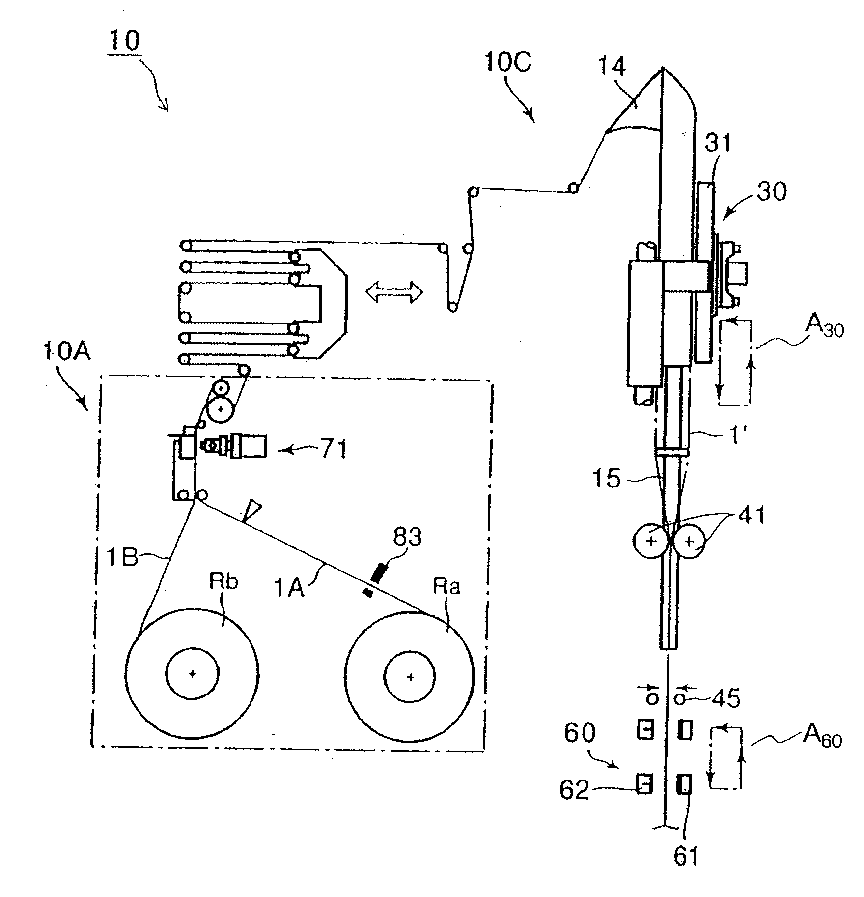
[0066]As shown in FIG. 3, packaging machine 10 of the present embodiment includes film feeding mechanism 10A that draws a film from feed rolls Ra and Rb, and joins film 1A and film 1B as needed. Further, packaging machine 10 includes packaging mechanism 10C that forms the film unrolled from film feeding mechanism 10A into a tubular shape, and that continuously manufactures a packaging bag by forming a vertical sealed portion and a lateral sealed portion thereon as needed.

[0067]As film feeding mechanism 10A, a proposed film feeding mechanism, which includes a general configuration for such a packaging machine, can be used. Film feeding mechanism 10A shown in FIG. 3 uses two feed rolls Ra and Rb, and is configured such that, for example, when film 1A of feed roll Ra has been used up, film 1B of feed roll Rb is continuously unrolled. It should be noted that FIG. 3 shows that film 1A is drawn into a side of the packaging mechanism 10C as a film on the using side, and that film 1B is hel...


PUM

PropertyMeasurementUnit
timeaaaaaaaaaa
timeaaaaaaaaaa
timeaaaaaaaaaa

Abstract

There is provided a vertical filling-packaging machine capable of feeding fluidized content material into a tubular film with good quantitative accuracy and in which air bubbles are mixed into the content material. The packaging machine according to the present invention performs an operation of feeding content material through injection nozzle (15) into tubular film (1′) that includes a bottom portion. This packaging machine performs an operation of transporting the tubular film downward, and an operation of tightly sealing the tubular film by heat sealing using lateral sealing mechanism (60). Lower end (15a) of the injection nozzle is configured to be immersed in the content material throughout entirety of the series of packaging operations, and the operation of feeding the content material starts in a state in which the injection port of the injection nozzle is immersed in the content material.

Description

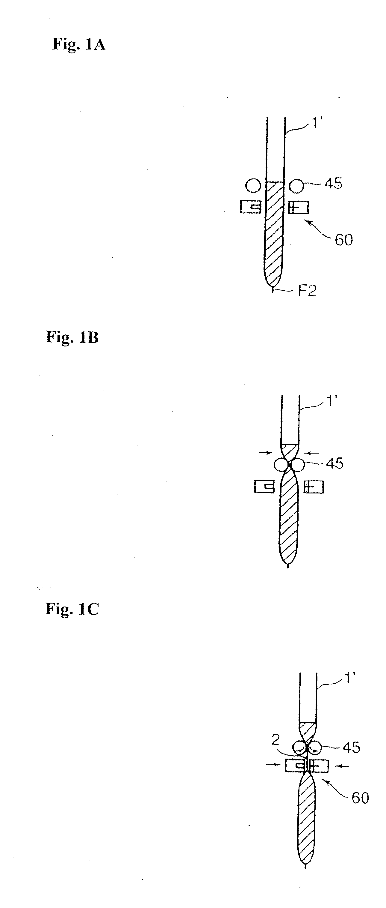
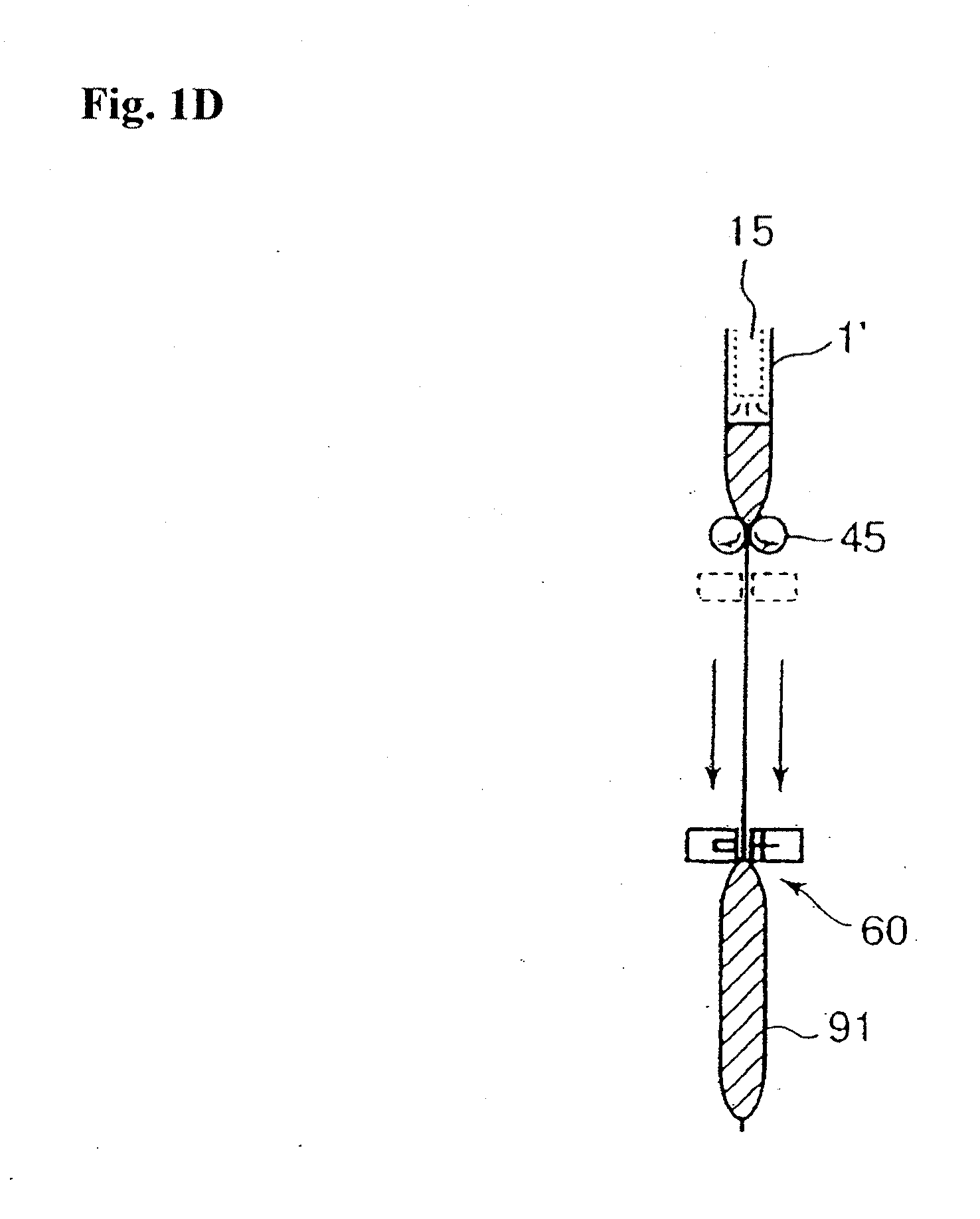
TECHNICAL FIELD[0001]The present invention relates to a vertical filling-packaging machine which forms a long film drawn from a feed roll into a tubular film and feeding content material thereinto, thereby manufacturing a packaging bag (packaged product), and more particularly to a vertical filling-packaging machine which feeds the content material through an injection nozzle into the tubular film that includes a bottom portion.BACKGROUND ART[0002]There has been known a packaging machine which continuously manufactures a packaging bag filled with content material such as liquid (for example, see Japanese Patent Laid-Open No. 2005-112359). The packaging machine manufactures the packaging bag by folding a long sheet of film drawn from a feed roll to form a tubular shape and by injecting the content material into the tubular film or forming a predetermined seal portion. Hereinafter, a typical packaging operation will be described with reference to FIG. 1.[0003]FIG. 1A illustrates an in...

Claims


Application Information

Patent Timeline
Patent Type & Authority Applications(United States)
IPC IPC(8): B65B9/06B65B9/20
CPCB65B9/2007B65B9/2028B65B51/303B65B41/16B65B9/213
Inventor TSURUTA, ORIHIRONAGAI, KATSUMI
Owner ORIHIRO ENGINEERING CO LTD
Learn More