
Earmuff device

a technology of earmuffs and earmuffs, which is applied in the field of earmuffs, can solve the problems of wearer discomfort, wearer ache or affect, and wearer's regular clothes cannot protect ears well, and achieve the effect of saving storage spa

Inactive Publication Date: 2009-08-20
SOUND TEAM ENTERPRISE
View PDF25 Cites 32 Cited by
  • Summary
  • Abstract
  • Description
  • Claims
  • Application Information

AI Technical Summary

Benefits of technology

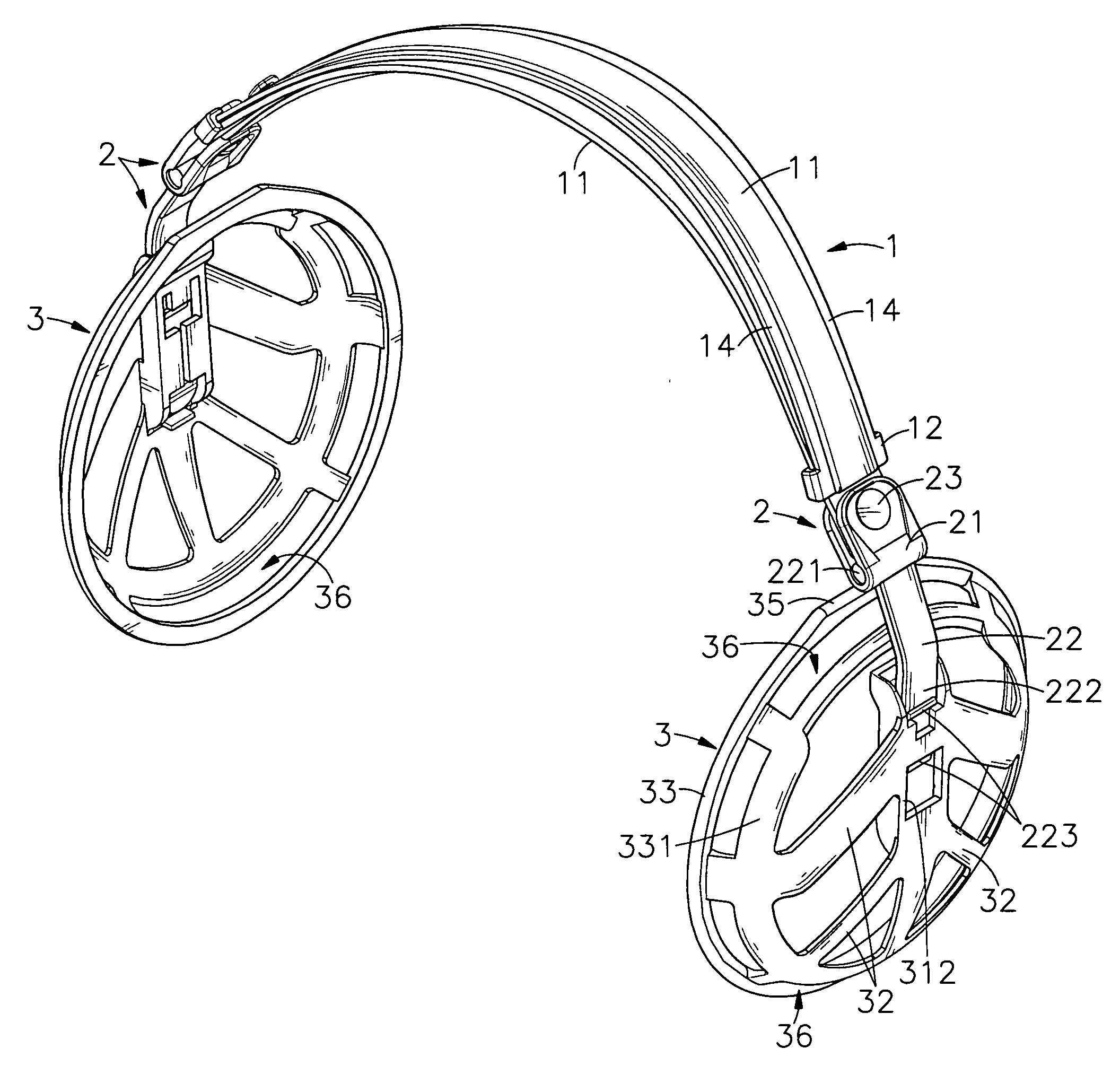
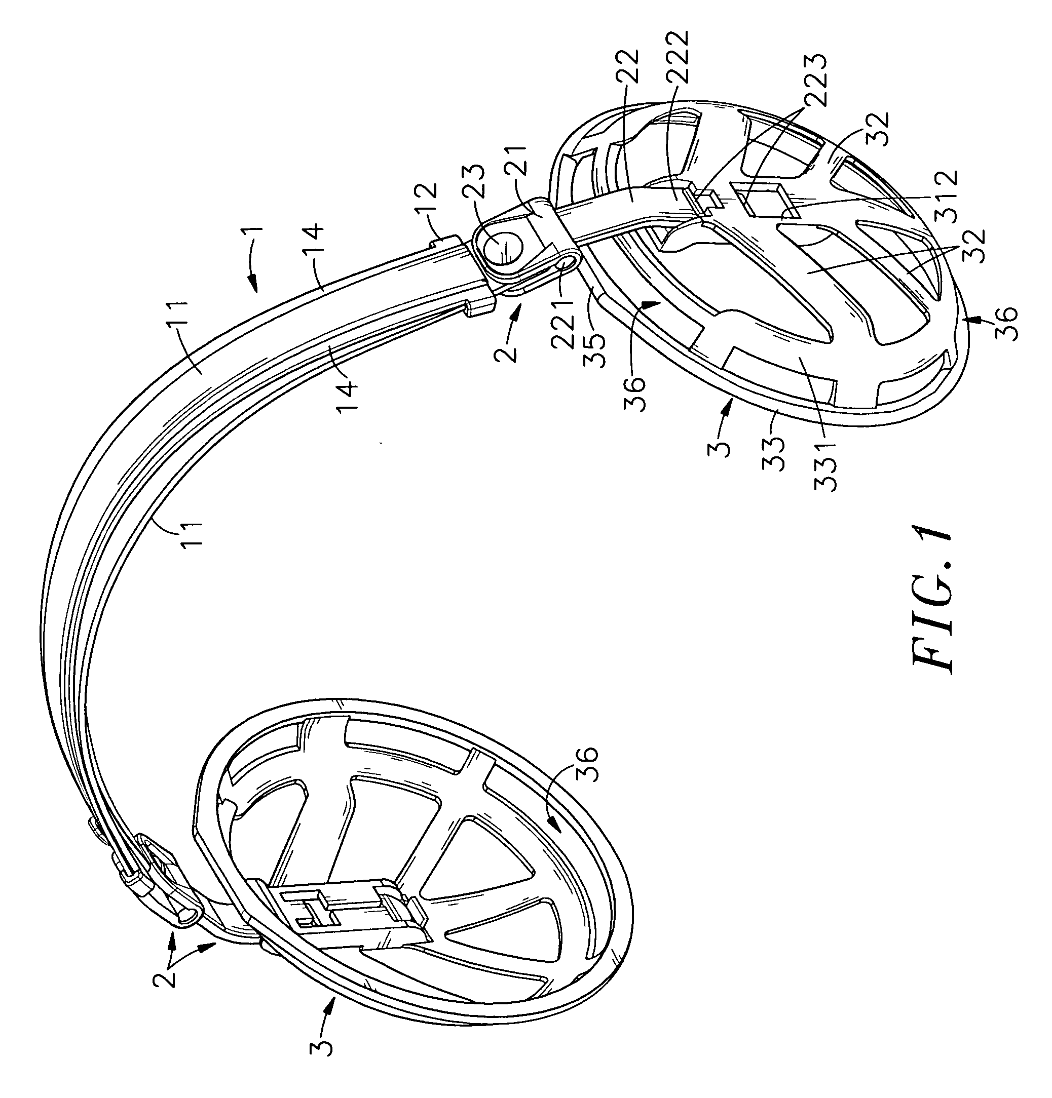
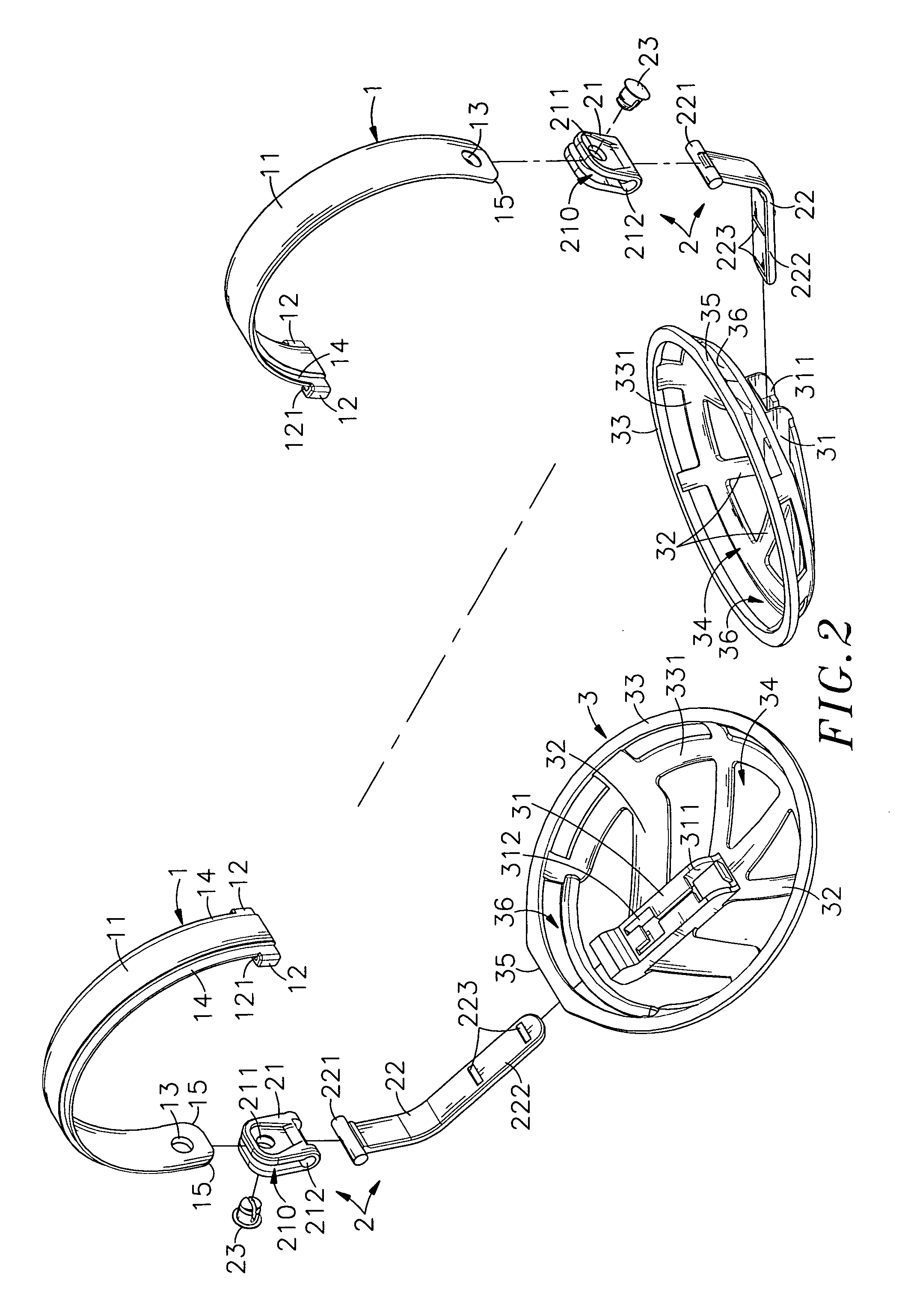
[0014]The present invention has been accomplished to provide an earmuff device that eliminates the aforesaid drawbacks. According to one aspect of the present invention, the earmuff device is comprised of a headpiece, two earmuff cups, two connecting devices respectively connecting the earmuff cups to the headpiece, and two earmuff cushions respectively covered on the earmuff cups. The headpiece is comprised of two smoothly arched bands that are overlapped on each other and axially slidable relative to each other. Each band has a coupling block disposed at one end and defining an insertion slot, and two sliding grooves bilaterally extending along the length. One band is inserted through the insertion slot of the other band and the coupling block of one band is slidably coupled to the sliding grooves of the other band so that the two bands are kept in a parallel manner and can be moved relative to each other to adjust the length of the headpiece. Because the sliding grooves bilaterally extend along the length of the respective band, the two opposite lateral sides of each band are relatively thinner. Therefore, the stress is concentrated on the middle part of each band during a use of the earmuff device, preventing distortion of the earmuff device.
[0015]According to another aspect of the present invention, each connecting device comprises an U-lug pivotally coupled to one end of one band of the headpiece, and a connecting strip pivoted to the U-lug and fastened to one earmuff cup. Therefore, the user can adjust the earmuff cups forwards and backwards as well as leftwards and rightwards. Further, each band has a chamfered end edge kept in friction engagement with the associating U-lug so that the U-lug can be positively positioned in one angular position relative to the associating band.
[0018]According to still another aspect of the present invention, the U-lugs of the connecting devices can be turned relative to the headpiece and the earmuff cups can be turned with the associating connecting strips relative to the associating U-lugs so that the earmuff device can be received in a compact condition, saving the storage space.

Problems solved by technology

When walking in a high mountain, snow land and outdoors during a winter season, regular clothes cannot well protect the ears, and the ears may ache or may be affected by frostbite.
1. The earmuff device can be worn on the user's head from the top or back side in one single direction.
2. The protruding ring end of each band of the headpiece A is kept in contact with the wearer's head, causing the wearer to feel uncomfortable.
3. Because the two bands of the headpiece A have a uniform transverse thickness, the headpiece A may be twisted easily. Further, because the angular position of the earmuffs B is not adjustable relative to the headpiece A, the earmuff device may fall from the wearer's head easily by an external force.
4. Because the earmuff device simply utilizes the small fastening member C to secure the earmuffs B to the headpiece A, the connection area between the earmuffs B and the headpiece A may break easily when the wearer adjust the position of the earmuffs B.
5. The earmuffs B have low structural strength and low grasping force. In consequence, the earmuffs B cannot cover the wearer's ears positively.
6. When the earmuff device is not in use, the user cannot receive the earmuff device in a collapsed condition with the earmuffs B attached together to save storage space. When receiving the earmuff device, the earmuff device may be broken accidentally.
7. The earmuff device is packed in the assembled condition. Therefore, this design does not allow the headpiece and the earmuffs to be separately wrapped with a respective fabric covering.

Method used


Image

  • Earmuff device
  • Earmuff device
  • Earmuff device

Examples


Embodiment Construction

[0035]Referring to FIGS. 1, 2, 10 and 11, an earmuff device is shown comprising a headpiece 1, two connecting devices 2, two earmuff cups 3 and two earmuff cushions 4.

[0036]The headpiece 1 is comprised of two smoothly arched bands 11 that are overlapped on each other and axially slidable relative to each other. Each band 11 has a first end provided with a chamfered end edge 15 and provided with a through hole 13, a second end opposing to the first end and provided with a coupling block 12 that defines an insertion slot 121, and two sliding grooves 14 bilaterally extending along the length between the first end and the second end. By means of inserting the first end of one band 11 through the insertion slot 121 of the coupling block 12 of the other band 11, the two bands 11 are coupled together and axially slidable relative to each other to adjust the combined length, and the sliding grooves 14 of one band 11 guide sliding movement of the coupling block 12 of the other band 11.

[0037]...


PUM


Abstract

An earmuff device is disclosed to include a headpiece formed of two smoothly arched bands that are overlapped on each other and axially slidable relative to each other, two earmuff cups each having a cup base, a gradual enlargement cup rim and a plurality of radial ribs radially connected between the cup base and the gradual enlargement cup rim, two U-lugs respectively pivotally connected to the bands of the headpiece, two connecting strips each having one end pivoted to one U-lug and the other end fastened to one earmuff cup, two earmuff cushions respectively covering the earmuff cups, and a soft sleeve sleeved onto the headpiece and connected between the earmuff cushions. The earmuff device allows a user to conveniently adjust the length of the headpiece as well as the angular position of the headpiece relative to the earmuff cups.

Description

[0001]This application claims the priority benefit of Taiwan patent application number 097105463 filed on Feb. 15, 2008.BACKGROUND OF THE INVENTION[0002]1. Field of the Invention[0003]The present invention relates to earmuffs and more particularly, to an earmuff device that allows the wearer to conveniently adjust the length of the headpiece as well as the angular position of the headpiece relative to the earmuff cups. Further, the earmuff device can be received in a collapsed manner with the two earmuff cups attached together to save storage space.[0004]2. Description of the Related Art[0005]In winter or cold places, people usually wear heavy clothes, muffler and gloves to keep the body and the hands warm. When walking in a high mountain, snow land and outdoors during a winter season, regular clothes cannot well protect the ears, and the ears may ache or may be affected by frostbite. For keeping the ears warm, earmuffs shall be used.[0006]FIG. 16 illustrates a conventional earmuff ...

Claims


Application Information

Patent Timeline
IPC IPC(8): A61F11/14
CPCA61F11/06
Inventor CHIANG, TSUNG-PAI
Owner SOUND TEAM ENTERPRISE
Learn More