Vacuum cleaner

a vacuum cleaner and vacuum technology, applied in the field of vacuum cleaners, can solve the problems of high counter-voltage, and achieve the effect of effective filter cleaning

Inactive Publication Date: 2009-08-20
ALFRED KARCHER GMBH & CO KG
View PDF58 Cites 17 Cited by
  • Summary
  • Abstract
  • Description
  • Claims
  • Application Information

AI Technical Summary

Benefits of technology

[0033]The configuration of the vacuum cleaner according to the invention makes it possible for external air to act on the side of the at least one filter, which faces away from the dirt collection tank, for a short time during normal suction operation and for this air to be removed by suction within a short time by means of the suction unit which is in flow connection with the filter even when the closing valve is opened. It is favorable when the valve member carries out a continuous movement back into its closing position via its open position, proceeding from its closing position, during the cleaning of the filter. With such a configuration, the valve member will, first of all, be accelerated powerfully in the direction away from the valve seat when the closing valve is opened and, subsequently, braked powerfully with the aid of the closing spring and, preferably, with the aid of the flexible stop element and reversed in its direction of movement in order to be accelerated again in the direction towards t

Problems solved by technology

When the supply of current is interrupted, the inductivity re

Method used


Image

  • Vacuum cleaner
  • Vacuum cleaner
  • Vacuum cleaner

Examples


Embodiment Construction

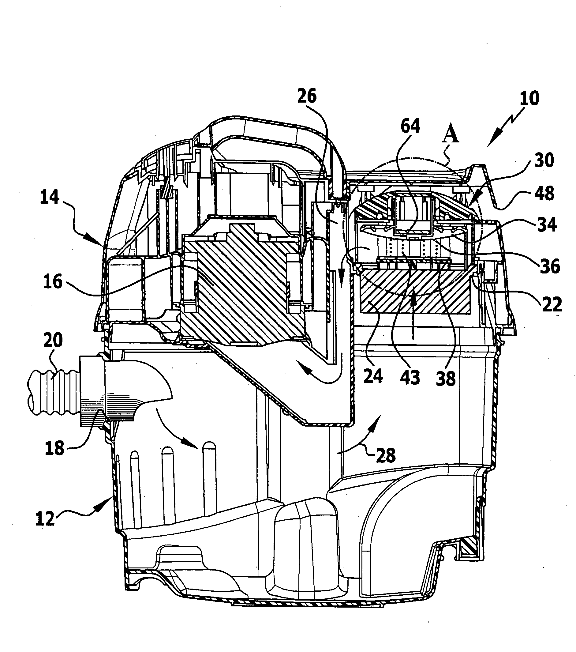
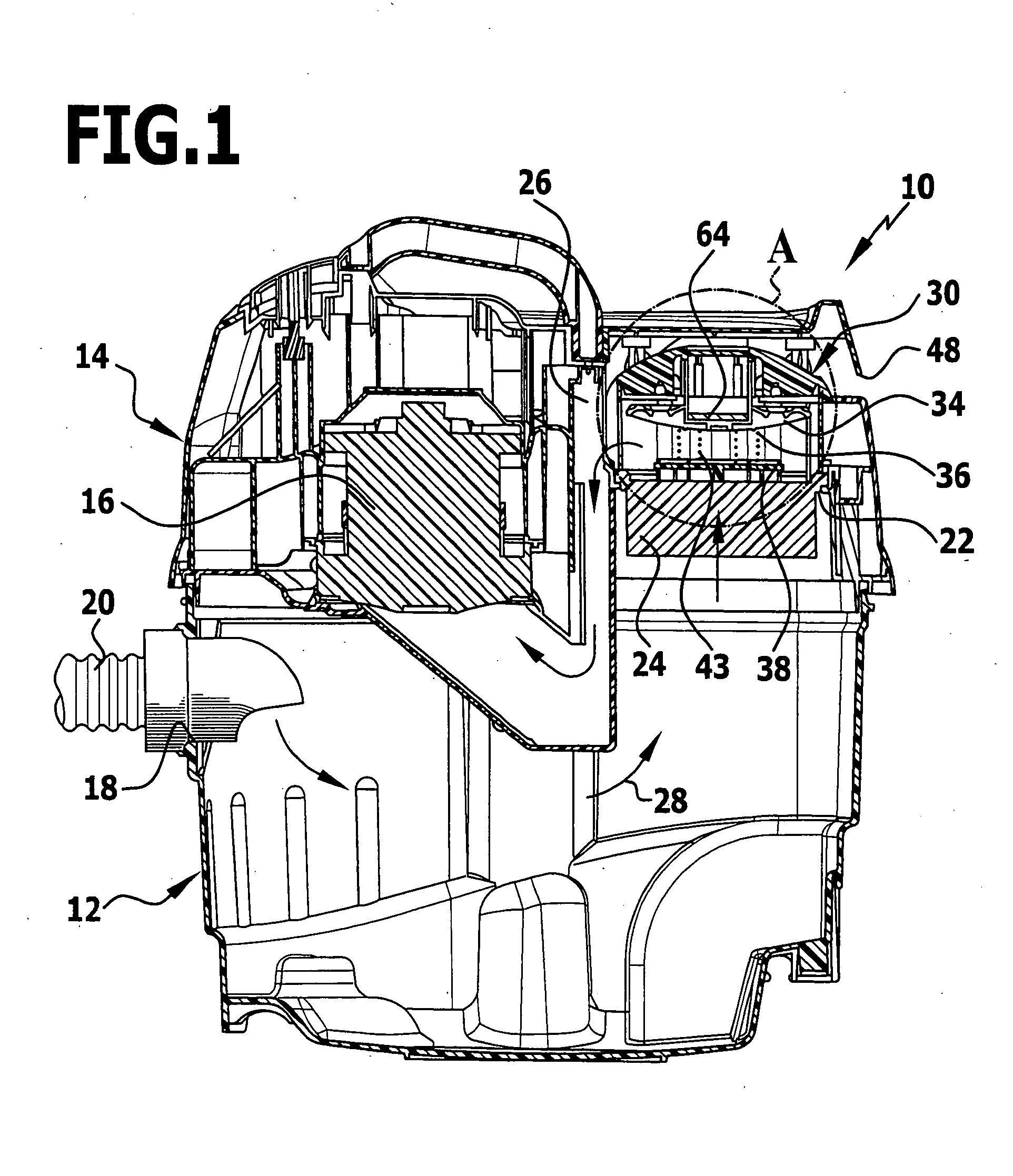
[0039]In the drawings, a vacuum cleaner 10 is illustrated schematically with a lower part which forms a dirt collection tank 12 and with an upper part 14 which is placed on the lower part and accommodates a suction unit 16. The dirt collection tank 12 comprises a suction inlet 18, to which a suction hose 20 can be connected. A suction nozzle can be connected to the free end of the suction hose 20 which is not illustrated in the drawings in order to achieve a better overview. Alternatively, it may be provided for the suction hose 20 to be connected to a machining tool, for example, a drilling unit or a milling unit so that dust which occurs during operation of the machining tool can be sucked in.

[0040]The upper part 14 forms a suction outlet 22 for the dirt collection tank 12. A folded filter 24 is held on the suction outlet 22 and an extraction line in the form of a suction channel 26 is connected to the filter. The folded filter 24 is permanently in flow connection with the suction...


PUM

PropertyMeasurementUnit
Timeaaaaaaaaaa
Timeaaaaaaaaaa
Timeaaaaaaaaaa

Abstract

The invention relates to a vacuum cleaner with a dirt collection tank which has a suction inlet and is in flow connection with at least one suction unit via at least one filter and at least one extraction line, and with at least one external air inlet which opens into the extraction line downstream of the at least one filter and can be closed by means of at least one closing valve, wherein the at least one closing valve has a valve member which can be moved back and forth between a closing position and an open position, wherein it is acted upon permanently by a closing spring with a closing force and in the closing position, in addition, by a magnetic holding device with a magnetic holding force. In order to develop the vacuum cleaner further in such a manner that it makes a particularly effective cleaning of the at least one filter possible, it is suggested in accordance with the invention that the magnetic holding device comprise an electromagnet with a magnetic core and a coil which can be acted upon with current for the purpose of closing the closing valve, wherein at least one electrical component, which takes up at least some of the energy stored in the coil when the current acting on the coil ceases, is connected in parallel to the coil.

Description

[0001]This application is a continuation of International application No. PCT / EP2006 / 007541 filed on Jul. 29, 2006.[0002]The present disclosure relates to the subject matter disclosed in International application No. PCT / EP2006 / 007541 of Jul. 29, 2006, which is incorporated herein by reference in its entirety and for all purposes.BACKGROUND OF THE INVENTION[0003]The invention relates to a vacuum cleaner with a dirt collection tank which has a suction inlet and is in flow connection with at least one suction unit via at least one filter and at least one extraction line, and with at least one external air inlet which opens into the extraction line downstream of the at least one filter and can be closed by means of at least one closing valve, wherein the at least one closing valve has a valve member which can be moved back and forth between a closing position, in which it abuts on a valve seat, and an open position, in which it is spaced from the valve seat, wherein it is acted upon pe...

Claims


Application Information

Patent Timeline
IPC IPC(8): A47L9/00
CPCA47L9/20F16K31/404B01D2273/28B01D46/521
Inventor STEWEN, CHRISTIANECKSTEIN, DANIELLANGEN, THORSTENBENZLER, GOTTFRIED
Owner ALFRED KARCHER GMBH & CO KG
Why Eureka
Try Eureka