Monitoring method and system for determining rack airflow rate and rack power consumption

a monitoring method and airflow rate technology, applied in the direction of volume/mass flow by differential pressure, instrumentation, testing/calibration for volume flow, etc., can solve problems such as cooling challenges, recirculation problems, and approach becoming problemati

Active Publication Date: 2009-08-20
LENOVO GLOBAL TECH INT LTD
View PDF8 Cites 71 Cited by
  • Summary
  • Abstract
  • Description
  • Claims
  • Application Information

AI Technical Summary

Problems solved by technology

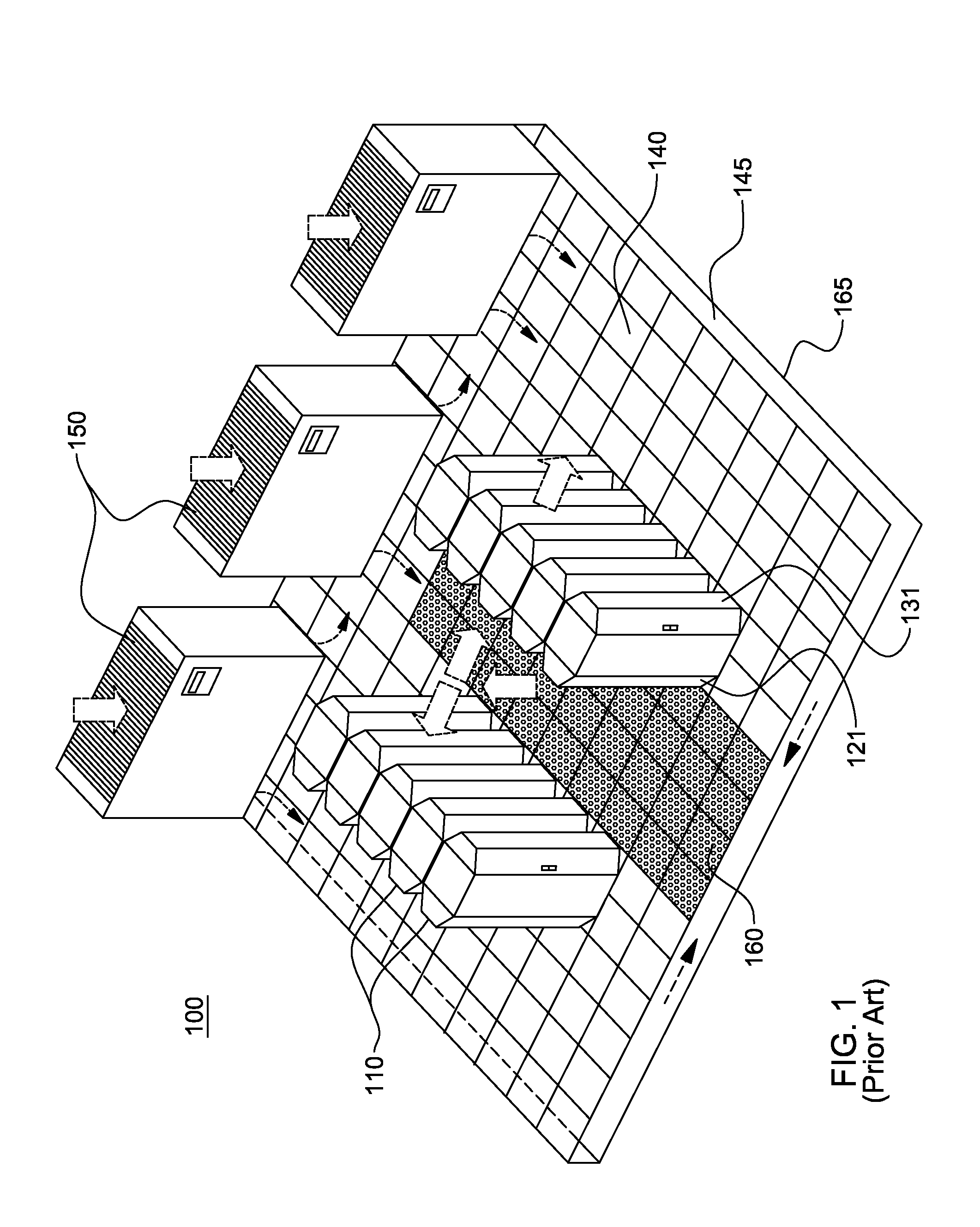
This trend poses a cooling challenge at both the module and system level.
However, this approach is becoming problematic at the rack level in the context of a computer installation (i.e., a data center).
In such installations not only will the room air-conditioning be challenged, but the situation may also result in recirculation problems with some fraction of the “hot” air exiting one rack unit being drawn into the air inlet of the same rack or a nearby rack.
This recirculating flow is often extremely complex in nature, and can lead to significantly higher rack inlet temperatures than expected.
This increase in cooling air temperature may result in components exceeding their allowable operating temperature and in a reduction in long term reliability of the components.

Method used


Image

  • Monitoring method and system for determining rack airflow rate and rack power consumption
  • Monitoring method and system for determining rack airflow rate and rack power consumption
  • Monitoring method and system for determining rack airflow rate and rack power consumption

Examples


Embodiment Construction

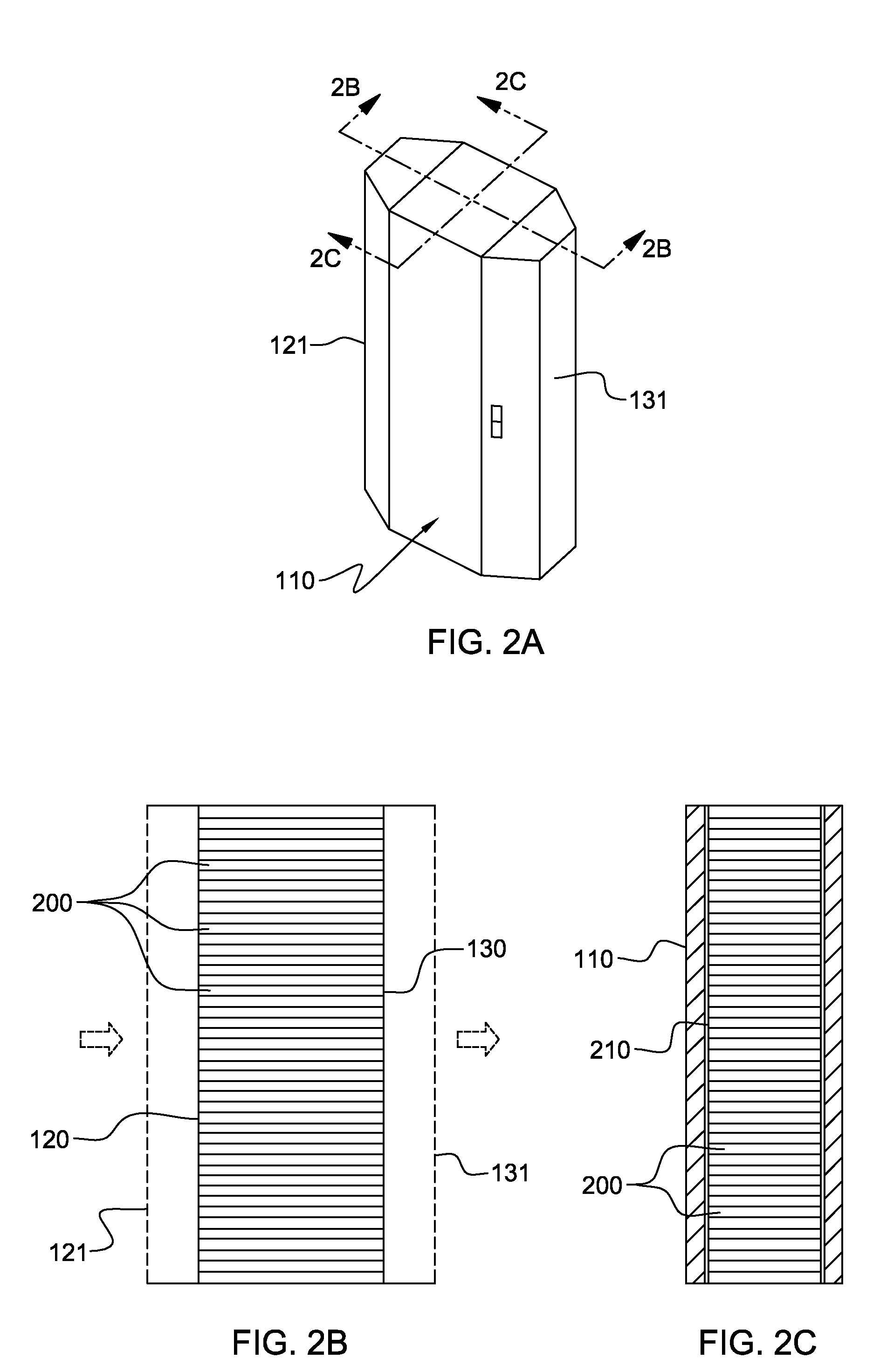
[0026]As used herein, the terms “electronics rack”, “rack-mounted electronic equipment”, and “rack unit” are used interchangeably, and unless otherwise specified include any housing, frame, rack, compartment, blade server system, etc., having one or more heat generating components of a computer system or electronics system, and may be, for example, a stand alone computer processor having high, mid or low end processing capability. In one embodiment, an electronics rack may comprise multiple electronics subsystems, each having one or more heat generating components disposed therein requiring cooling. “Electronics subsystem” refers to any sub-housing, blade, book, drawer, node, compartment, etc., having one or more heat generating electronic components disposed therein. Each electronics subsystem of an electronics rack may be movable or fixed relative to the electronics rack, with the electronics drawers of a multi-drawer rack unit and blades of a blade center system being two example...


PUM


Abstract

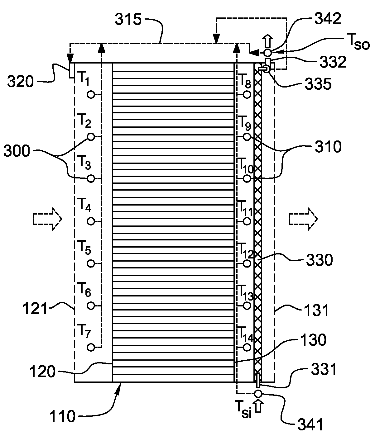
Monitoring method and system are provided for dynamically determining rack airflow rate and rack power consumption employing a heat exchanger disposed at an air outlet side of the electronics rack. The method includes: sensing air temperature at the air outlet side of the electronics rack, sensing coolant temperature at a coolant inlet and coolant temperature at a coolant outlet of the heat exchanger, and determining airflow rate through the electronics rack; and outputting the determined airflow rate through the electronics rack. The determining employs the sensed air temperature at the air outlet side of the rack and the sensed coolant temperatures at the coolant inlet and outlet of the heat exchanger. In one embodiment, the heat exchanger is an air-to-air heat exchanger, and in another embodiment, the heat exchanger is an air-to-liquid heat exchanger.

Description

TECHNICAL FIELD[0001]The present invention relates in general to computer room or data center monitoring and management, and more particularly, to monitoring methods and systems for ascertaining airflow rate through and power consumption of an electronics rack to facilitate management of cooling within a data center containing one or more electronics racks.BACKGROUND OF THE INVENTION[0002]The power dissipation of integrated circuit chips, and the modules containing the chips, continues to increase in order to achieve increases in processor performance. This trend poses a cooling challenge at both the module and system level. Increased airflow rates are needed to effectively cool high power modules and to limit the temperature of air that is exhausted into the computer center.[0003]In many large server applications, processors along with their associated electronics (e.g., memory, disk drives, power supplies, etc.) are packaged in removable drawer configurations stacked within a rack...

Claims


Application Information

Patent Timeline
Patent Type & Authority Applications(United States)
IPC IPC(8): G01F1/68
CPCG01F1/34H05K7/20836G01F25/0007G01F1/68G01F25/10
Inventor CAMPBELL, LEVI A.CHU, RICHARD C.ELLSWORTH, JR., MICHAEL J.IYENGAR, MADHUSUDAN K.SIMONS, ROBERT E.
Owner LENOVO GLOBAL TECH INT LTD
Why Eureka
Try Eureka