
Disk inspection apparatus and method

Inactive Publication Date: 2009-08-20
FUJIFILM CORP
View PDF8 Cites 8 Cited by
  • Summary
  • Abstract
  • Description
  • Claims
  • Application Information

AI Technical Summary

Benefits of technology

[0012]The present invention allows a flat portion and an edge portion of a disk to be simultaneously inspected. Particularly, the illumination device of the present invention allows for illumination in a necessary and sufficient range, and prevention of abnormal reflection and blooming in the edge portion, further preventing an undesired image from showing up because of pattern illumination in the range of delivery of illumination light approximately coincided with a shape of the inspection area.
[0049]According to the present invention, concerning a disk to be inspected, a flat portion and an edge portion of the disk can be simultaneously inspected by obtaining a taken image of the disk surface including the edge, and an inspection time also can be reduced.

Problems solved by technology

However, JP-A-2000-9453 describes the inspection machine dedicated to an end surface which was designed to inspect only an outer circumference end surface (edge) of a hard disk, and the apparatus disclosed in JP-A-2000-9453 cannot inspect a surface and an inner circumference end surface of a disk.
Also, the technology described in JP-A-2000-9453 relates to measurement of a strength in the direct direction of laser beams with which a disk end surface is radiated, and to measurement of a strength of diffusive reflection from an inner surface of a divided reflector, and accordingly it is difficult to verify the measurement result because separation between a defect having a small effect, such as a scratch on a disk end surface, and dust (the dust having a large effect) is inadequately provided from the measured information, and measurement principles of the technology, further, is not intended to provide an image reflecting an edge portion.
Granted that inspection of both surfaces are achieved, it is necessary to combine two or more apparatuses and to turn around a disk to inspect the back face, and a facility, accordingly, has to be made expensive and large, requiring an installation site.
Also, because inspection of each disk is repeated by handling each time, handling of the disk may generate a particle, thereby quality may be degraded and there may be many issues concerning throughput.

Method used


Image

  • Disk inspection apparatus and method
  • Disk inspection apparatus and method
  • Disk inspection apparatus and method

Examples


Embodiment Construction

[0087]First, there will be description of a configuration for a chuck apparatus of a disk used for a disk inspection apparatus according to an embodiment of the present invention. In addition, in this embodiment, a disk inspection apparatus and a chuck apparatus of a magnetic disk used for a hard disk drive, by way of example, will be described.

[Exemplary Configuration of Chuck Apparatus of Disk]

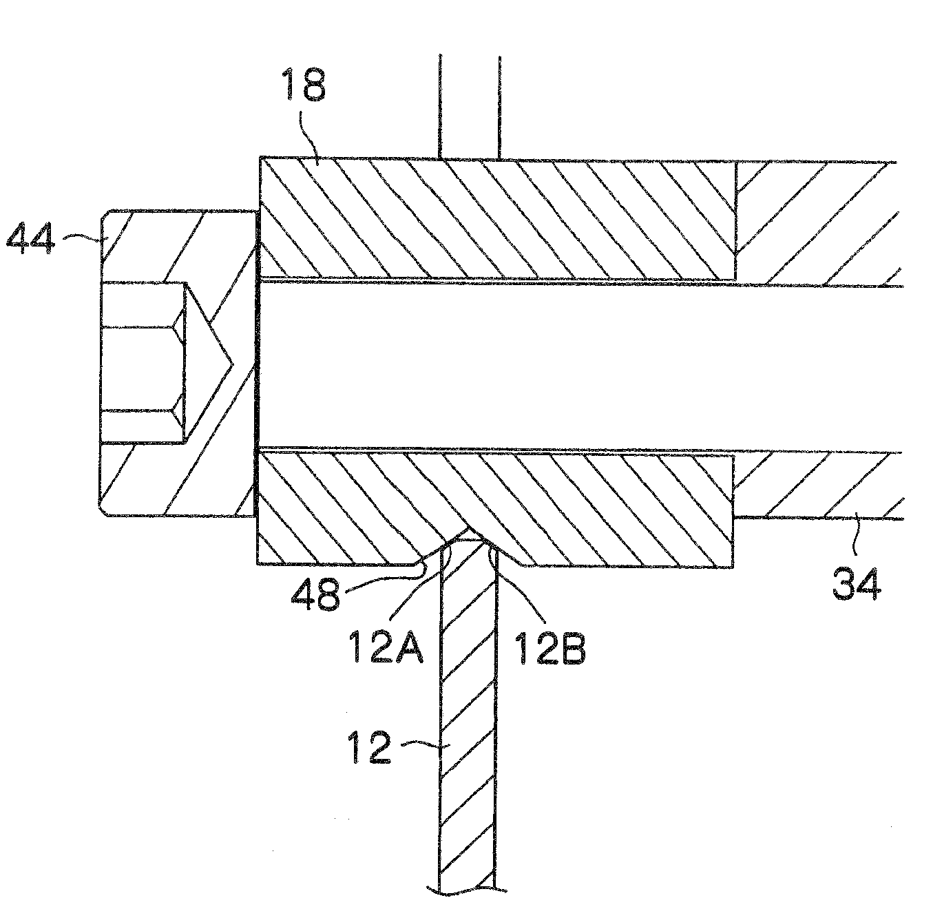
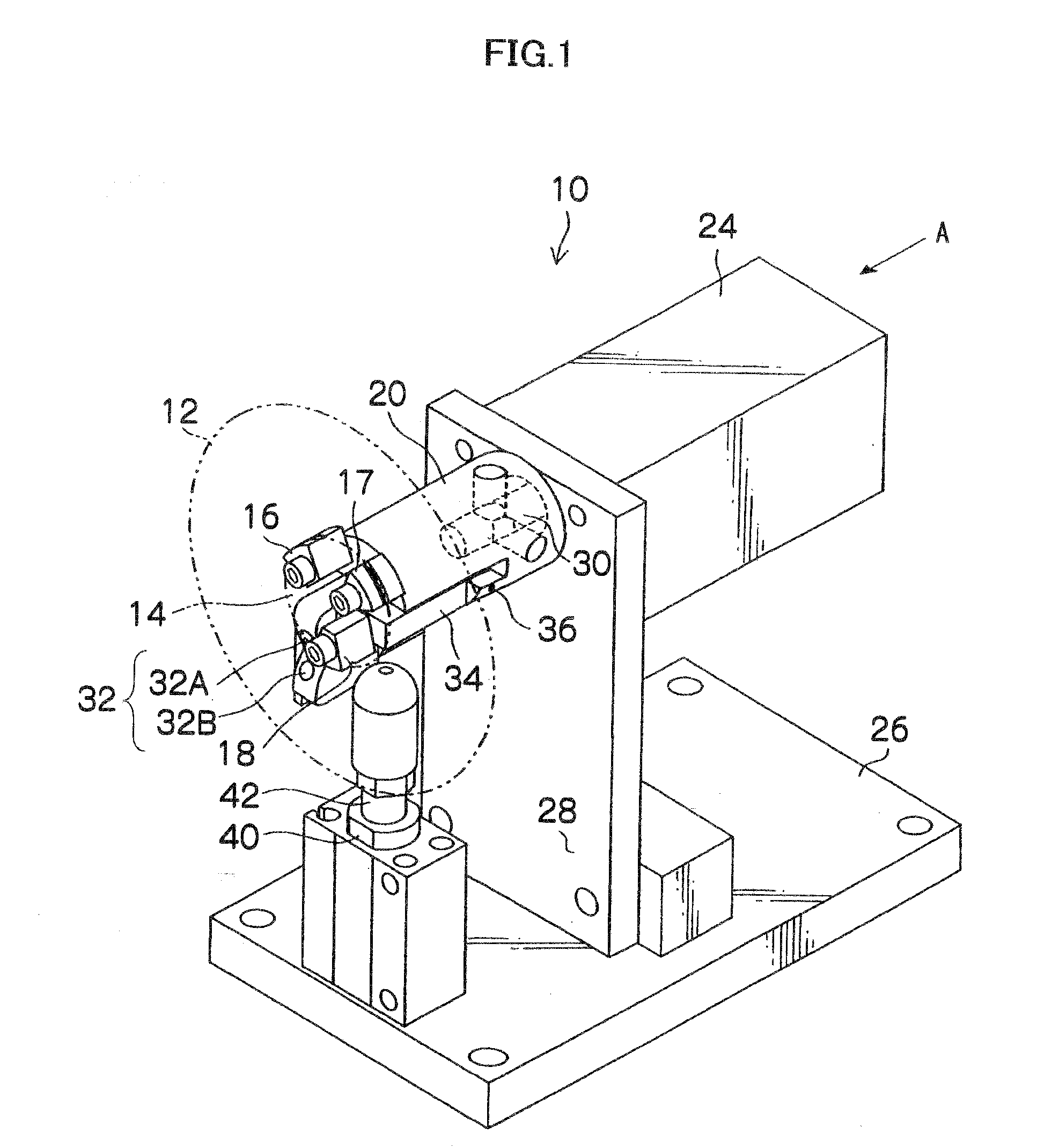
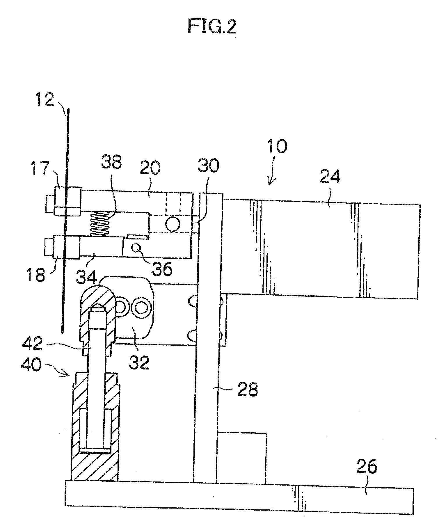
[0088]FIG. 1 is a perspective view showing an exemplary configuration of a chuck apparatus of a disk used for a disk inspection apparatus according to an embodiment of the present invention. FIG. 2 is a side view of FIG. 1. As shown in these drawings, a chuck apparatus 10 according to this embodiment includes: a chuck body 20 having three claws 16, 17, 18 brought in contact with a circumference edge of a hole 14 (inner circumference surface of a disk 12) formed in the central portion of the disk 12; and a motor 24 for rotating the chuck body 20.

[0089]The motor 24 is fixed to a support plate ...


PUM


Abstract

A disk inspection apparatus according to the present invention comprises: a disk holding device which holds a disk; an illumination device which radiates an inspection area portion having a predetermined shape on a disk surface including an edge of the disk held by the disk holding device, with illumination light having an illumination light pattern which forms a range of delivery of illumination light having approximately the same shape as that of the inspection area; and an imaging device which includes, in the field of view, the inspection area portion on the disk surface including the edge illuminated by the illumination device, and takes an image of light reflected from the inspection area portion.

Description

BACKGROUND OF THE INVENTION[0001]1. Field of the Invention[0002]The present invention relates to a disk inspection apparatus and method, and in particular to a disk inspection method and apparatus suitable for inspecting contamination conditions of surfaces and end surfaces of a magnetic disk, an optical disk, a magnetic optical disk and the like used for a hard disk drive.[0003]2. Description of the Related Art[0004]Recently, a hard disk drive has had a denser recording density, and a head floating height has become immensely small. Accordingly, even a fine particle may cause a dropout, and there also may be increasing chances for a particle to bite into a head to damage data. In addition, movement of a particle on not only a recording surface but also an outer and inner circumference surfaces may cause the failure as described above. Especially an edge portion cannot avoid contact with a carrying case, a handling jig, a chuck in a facility and the like, and may constitute a source...

Claims


Application Information

Patent Timeline
IPC IPC(8): H04N7/18
CPCG01N21/9506
Inventor HAYASHI, YOICHIOKADA, SHINICHIRO
Owner FUJIFILM CORP
Features
  • Generate Ideas
  • Intellectual Property
  • Life Sciences
  • Materials
  • Tech Scout
  • Unparalleled Data Quality
  • Higher Quality Content
  • 60% Fewer Hallucinations
Learn More