
Signal processing apparatus, signal processing method, and storage medium

Active Publication Date: 2017-10-05
CANON KK
View PDF0 Cites 0 Cited by
  • Summary
  • Abstract
  • Description
  • Claims
  • Application Information

AI Technical Summary

Benefits of technology

The patent aims to provide a signal processing apparatus and method that can accurately extract a detection target signal from an input signal in a short period of time with high reliability. The technique uses stochastic resonance phenomenon and is useful in product inspection and the extraction of defective portions from images. The invention aims to overcome disadvantages of existing methods and provide a solution for accurate and fast signal processing.

Problems solved by technology

However, if the above inspection step uses Non-Patent Document 1 or the publication of Japanese Patent Laid-Open No. 2012-175371 in order to sufficiently increase the effect thereof, i.e., the robustness against the noise strength, many synthesis circuits or nonlinear circuits are required, which causes a concern of a complicated processing, an increased processing time, or an apparatus having a higher price.

Method used


Image

  • Signal processing apparatus, signal processing method, and storage medium
  • Signal processing apparatus, signal processing method, and storage medium
  • Signal processing apparatus, signal processing method, and storage medium

Examples


first embodiment

[0039]FIG. 4 is a block diagram for explaining the control configuration in the embodiment of FIG. 3D. The image processing apparatus 1 as a signal processing apparatus consists of a host PC for example. A CPU 301 executes various kinds of processing while using a RAM 302 as a work area in accordance with a program retained in an HDD 303. For example, the CPU 301 generates image data that can be printed by the complex machine 6 based on a command received from a user via a keyboard / mouse I / F 305 or a program retained by the HDD 303 and transfers this to the complex machine 6. The CPU 301 subjects the image data received from the complex machine 6 via a data transfer I / F 304 to predetermined processing based on the program stored in the HDD to display the result or various pieces of information on a not-shown display via a display I / F 306. Image data I(x), which is a target of the stochastic resonance processing of this embodiment as described later, is received from the complex mach...

second embodiment

[0089]This embodiment also uses a complex machine shown in FIG. 4 to FIG. 6B to extract a white stripe generated in the inspection patterns 701 to 704 shown in FIG. 7 based on the flowchart shown in FIG. 9. However, in this embodiment, the result obtained by performing the noise cut processing is multiplied by the result obtained by performing the stochastic resonance processing without performing the noise cut processing to calculate the product thereof based on which the judgment processing is performed.

[0090]FIG. 17 is a flowchart for explaining specific steps performed by the image processing apparatus 1 of this embodiment in the singular portion extraction processing of Step S3. When this processing is started, then the image processing apparatus 1 firstly generates, in Step S31, the inspection data S(x) based on multivalued RGB data stored in the RAM 312 in Step S2 of FIG. 9. This step is similar to Step S21 of FIG. 12.

[0091]Step S32 subjects the inspection data S(x) generated...


PUM


Abstract

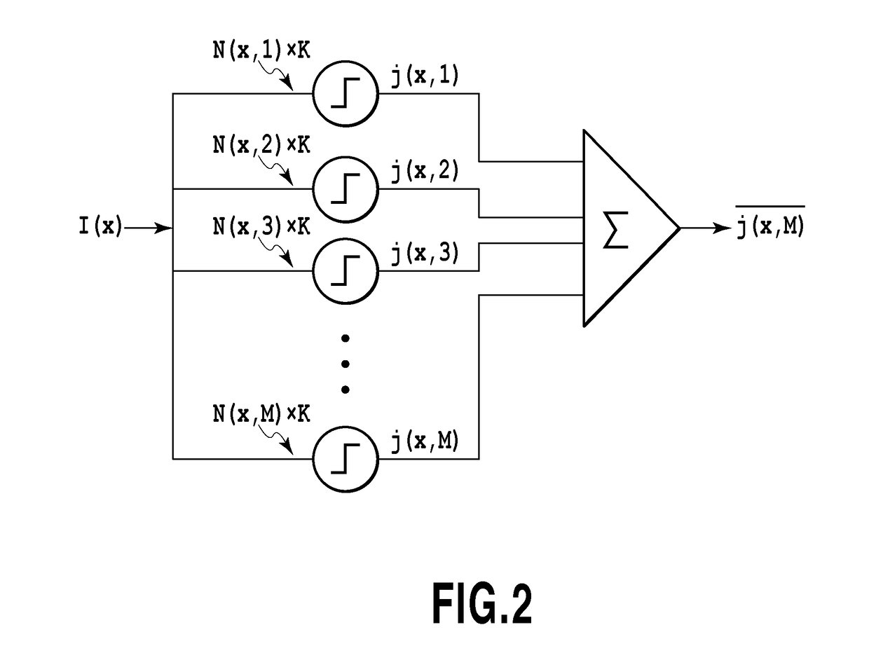
A signal processing apparatus includes a unit configured to generate noise cut data by deducting a predetermined noise value from values of respective signals constituting input data and a stochastic resonance processing unit configured to subject the noise cut data to a predetermined stochastic resonance processing. The predetermined stochastic resonance processing is processing to output, in a method of synthesizing a result of parallelly performing steps of adding new noise to the noise cut data to subject the resultant data to a binary processing, a value obtained in a case where the parallel number is infinite.

Description

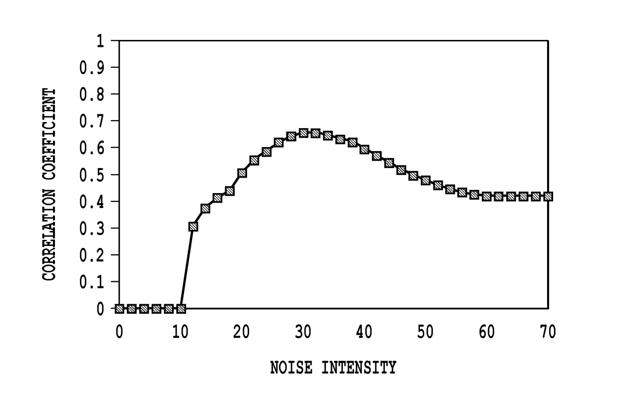
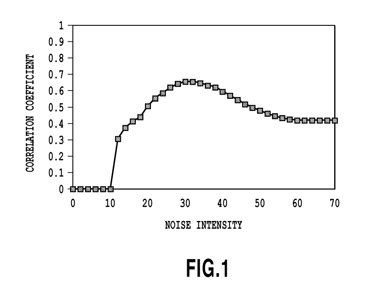
BACKGROUND OF THE INVENTIONField of the Invention[0001]The present invention relates to a signal processing apparatus and a signal processing method by which a detection target signal is extracted from an input signal in which the detection target signal is buried in noise.Description of the Related Art[0002]In order to extract a detection target signal from an input signal buried in noise, a stochastic resonance phenomenon is useful. The stochastic resonance phenomenon is a phenomenon in which an input signal buried in noise is further added with noise and the resultant signal is subsequently subjected to nonlinear processing to thereby emphasize a detection target signal. However, in such a stochastic resonance phenomenon, a correlation coefficient used as an evaluation value showing the performance of the detection result changes depending on the strength of added noise as shown in FIG. 1. In the case of FIG. 1, the correlation coefficient is maximum at a noise strength 30. Speci...

Claims


Application Information

Patent Timeline
IPC IPC(8): H04B1/10G01R23/16H04B17/345G01R29/26H04B17/336G06T5/00G10L21/0208
CPCH04B1/10G06T5/002G01R23/16H04B17/345G01R29/26H04B17/336G10L21/0208G06F3/121G06F3/1279H04N1/409H04N1/504G06V10/30G06F2218/04G06F2218/16G06T5/70
Inventor SUWA, TETSUYAISHIKAWA, TOMOKAZUTANAKA, WAKAKOHORI, SHINJIRO
Owner CANON KK
Features
  • Generate Ideas
  • Intellectual Property
  • Life Sciences
  • Materials
  • Tech Scout
  • Unparalleled Data Quality
  • Higher Quality Content
  • 60% Fewer Hallucinations
Learn More