Eureka AIR delivers breakthrough ideas for toughest innovation challenges, trusted by R&D personnel around the world.

Automatic inspection method and device for polar electronic component in circuit board

An electronic component and automatic inspection technology, applied in electrical components, electrical components and other directions, can solve the problems of low detection efficiency, inability to realize automatic inspection, and small automatic inspection range, so as to improve detection efficiency, improve inspection efficiency and check Accuracy, improved traceability effect

Inactive Publication Date: 2019-03-05
ZHUZHOU CSR TIMES ELECTRIC CO LTD
View PDF7 Cites 10 Cited by
  • Summary
  • Abstract
  • Description
  • Claims
  • Application Information

AI Technical Summary

Problems solved by technology

[0006] (1) This type of method can only realize the inspection of specific types of electronic components, and the circuit board includes a variety of polarized electronic components such as diodes, capacitors, and polarized IC chips. The scope of inspection is small;
[0007] (2) Since it is for the inspection of specific electronic components, the above method usually first manually determines the position of the electronic components, and then collects the images of the components, and there are many electronic components to be inspected in the circuit board, sampling the above When the method is used to detect the electronic components in the entire circuit board, the detection efficiency is still not high, and the automatic inspection of multiple electronic components with polarity in the entire circuit board cannot be realized

Method used


Image

  • Automatic inspection method and device for polar electronic component in circuit board
  • Automatic inspection method and device for polar electronic component in circuit board
  • Automatic inspection method and device for polar electronic component in circuit board

Examples


Embodiment Construction

[0046] The present invention will be further described below in conjunction with the accompanying drawings and specific preferred embodiments, but the protection scope of the present invention is not limited thereby.

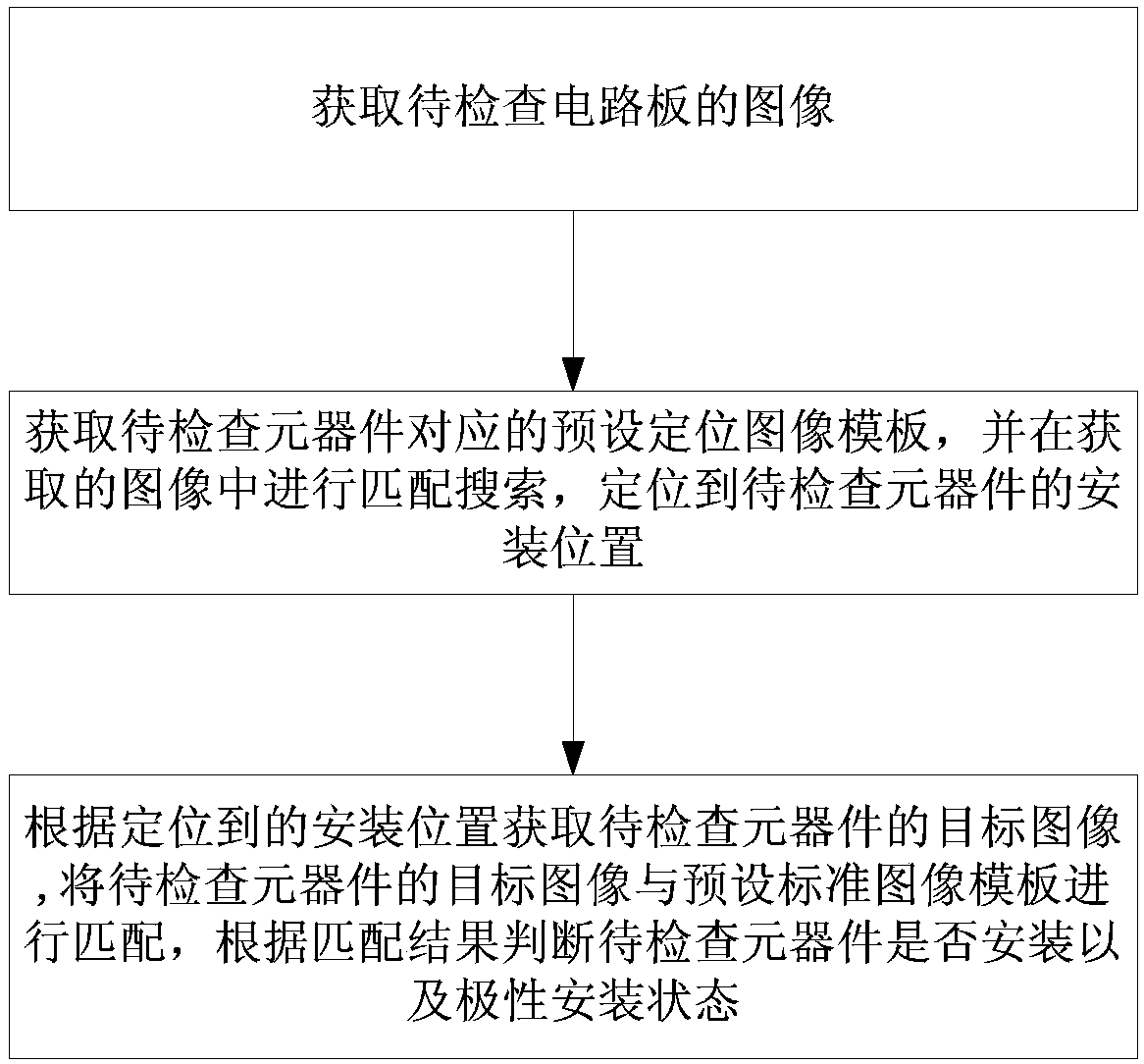
[0047] like figure 1 As shown, the automatic inspection method of polarized electronic components in the circuit board of this embodiment, the steps are:

[0048] S1. Image acquisition: acquire an image of the circuit board to be inspected.

[0049] This embodiment specifically uses a visual sensor to collect images of the circuit board to be inspected. The visual sensor can be composed of one or more graphic sensors, and is equipped with a light source and other auxiliary equipment. The visual sensor can specifically use a laser scanner, a line array or an area sensor. Array CCD cameras, TV cameras and digital cameras, etc.

[0050] In a specific embodiment, when the inspection is started, the circuit board to be inspected is placed in a closed inspection box...


PUM


Abstract

The invention discloses an automatic inspection method and device for a polar electric component in a circuit board. The method comprises the following steps: S1, obtaining an image of a to-be-inspected circuit board; S2, obtaining a preset positioning image template of the to-be-inspected element, performing matching search on the image obtained in the step S1, and positioning to a mounting position of the to-be-inspected element; S3, obtaining a target image of the to-be-inspected element according to the positioned mounting position, obtaining a preset standard image template correspondingto the to-be-inspected element, matching a target image of the to-be-inspected element with the preset standard image template and judging whether the to-be-inspected element is mounted and the polarity mounting state according to a matching result. The device comprises an image obtaining module, an element positioning module and a mounting inspection module. The method and the device in the invention can realize automatic inspection of various polar elements and have the advantages of simple implementation method, low inspection cost, high inspection efficiency and precision, wide range of application and the like.

Description

technical field [0001] The invention relates to the technical field of installation and inspection of electronic components, in particular to an automatic inspection method and device for polarized electronic components in a circuit board. Background technique [0002] The electronic components in the circuit board are installed according to specific positions and polarity directions. A circuit board is usually equipped with electronic components of different types and specifications. After the electronic components are installed on the circuit board and before normal use, usually It is necessary to check the installation of each electronic component in the circuit board to verify whether the installation is correct, especially to check the polarity of the electronic components. If the polarity is installed incorrectly, the circuit board will not work properly. [0003] The installation inspection of electronic components in circuit boards is usually performed manually one b...

Claims


Application Information

Patent Timeline
Patent Type & Authority Applications(China)
IPC IPC(8): H05K13/00H05K13/04H05K13/08
CPCH05K13/00H05K13/04H05K13/08
Inventor 周晓谢明明龙敏浩颜楚强田方斌方奇刘浩汤家师汪谢丹孙磊
Owner ZHUZHOU CSR TIMES ELECTRIC CO LTD
Why Eureka
Eureka Blog
Learn More