
An unmanned aerial vehicle calibration system and method of an instrument landing system

An instrument landing system and calibration method technology, applied in the aviation field, can solve problems such as flight calibration capability and efficiency not meeting requirements, flight operation, difficulty in effective control cycle, strict calibration requirements, etc., to save costs and personnel consumption, the equipment is light and easy to carry, and the effect of improving calibration efficiency

Inactive Publication Date: 2017-12-15
CIVIL AVIATION UNIV OF CHINA
View PDF7 Cites 10 Cited by
  • Summary
  • Abstract
  • Description
  • Claims
  • Application Information

AI Technical Summary

Problems solved by technology

However, this mode of task planning takes a long time, organization and coordination are difficult, and the calibration requirements are strict. It needs to stop the flight to cooperate with the calibration work, which affects normal flight operations, and it is difficult to effectively control the cycle. There are many uncertain factors and the calibration cost is very high. There are more and more civil airports, but there is only one organization that has obtained the qualification for verification. The flight verification capability and efficiency of the current domestic flight verification benchmark system are far from meeting the needs

Method used


Image

  • An unmanned aerial vehicle calibration system and method of an instrument landing system
  • An unmanned aerial vehicle calibration system and method of an instrument landing system

Examples


Embodiment Construction

[0021] The UAV verification system and method for the instrument landing system provided by the present invention will be described in detail below in conjunction with the accompanying drawings and specific examples. It should be understood that the examples described here are only used to illustrate and explain the present invention, and are not intended to limit the present invention. .

[0022] Such as figure 1 As shown, the UAV verification system of the instrument landing system provided by the present invention includes a calibration flight UAV 1 and a ground station 2; wherein:

[0023] The school flight UAV 1 includes the UAV body and the UAV airborne equipment; the UAV body is a remote control multi-rotor aircraft; the UAV airborne equipment is installed on the UAV body; the ground station 2 is the ground monitoring equipment ;

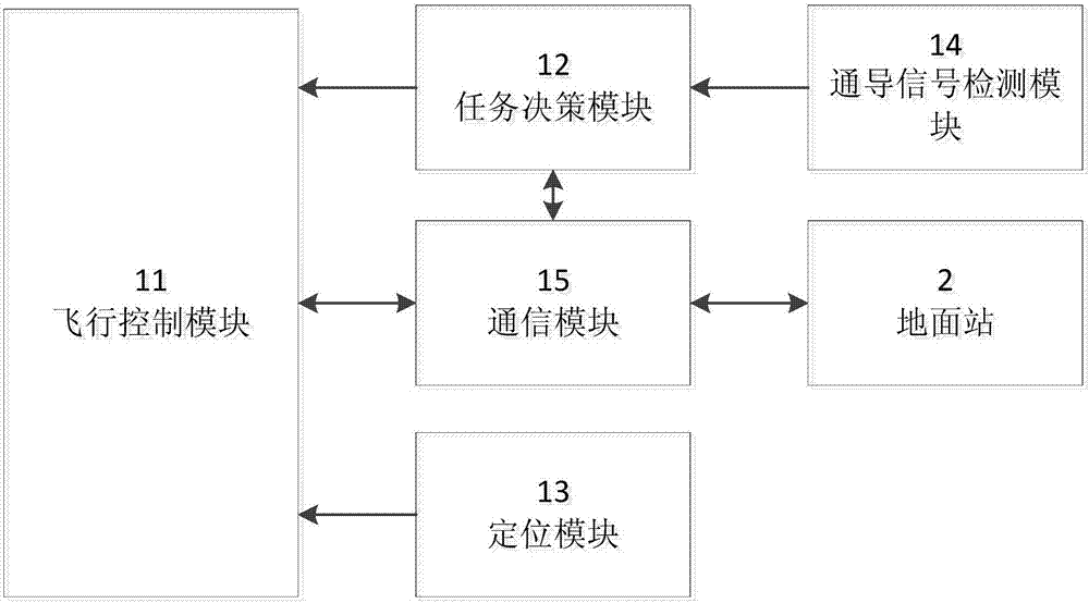
[0024] Such as figure 2 As shown, the UAV airborne equipment includes:

[0025] Flight control module 11, task decision-making module 1...


PUM


Abstract

An unmanned aerial vehicle calibration system and method of an instrument landing system are provided. The calibration system includes a flight calibrating unmanned aerial vehicle and a ground station. The flight calibrating unmanned aerial vehicle includes an unmanned aerial vehicle main body and an unmanned aerial vehicle onboard device. The unmanned aerial vehicle main body is a remote-controlled multi-rotor flight vehicle. The unmanned aerial vehicle onboard device is mounted on the unmanned aerial vehicle main body. The ground station is a ground monitoring device. Beneficial effects of the calibration system and method are that calibration of communication and navigation signals of the instrument landing system in an aircraft approach process can be simulated, thus greatly increasing the calibration efficiency, saving the cost and making examination precision high; and equipment is light and portable, flight calibrating steps are simplified, and two persons can complete all calibration tasks, thus making flight calibration more convenient and rapider. The method can meet various flight calibration index requirements of a civil aviation airport on the instrument landing system, can replace traditional flight calibration manners, and can save a large amount of cost and personal for the airport. The calibration system and method are highly automatic and intelligent, and ensure accuracy of the instrument landing system as landing guides and indicators.

Description

technical field [0001] The invention belongs to the field of aviation technology, in particular to an unmanned aerial vehicle calibration system and method for an instrument landing system. Background technique [0002] Instrument Landing System (ILS) is also translated as instrument landing system and blind landing system. It is the most widely used aircraft precision approach and landing guidance system, including localizer (LOC) system, glide beacon (GS) System, beacon (MB) system three parts. Its role is to realize the localizer and glideslope guidance by two beams of radio signals emitted from the ground, and establish a virtual glide line pointing from the runway to the air. The aircraft determines its relative position to the path through the onboard receiving equipment, so that the aircraft follows the path. Fly in the right direction to the runway and descend smoothly, and finally achieve a safe landing. According to the requirements of the Civil Aviation Organiza...

Claims


Application Information

Patent Timeline
Patent Type & Authority Applications(China)
IPC IPC(8): G01C25/00G01C23/00
CPCG01C23/005G01C25/00
Inventor 高庆吉闫婷王立忠赵迎春牛国臣
Owner CIVIL AVIATION UNIV OF CHINA
Learn More