Light shieldling structure of an optical device

a technology of optical devices and shielding structures, applied in the field of light shielding structures of optical devices, can solve the problems of increased number of elements and increased man-hours, and achieve the effect of reducing the number of elements and increasing the man-hours

Inactive Publication Date: 2009-08-20
HOYA CORP
View PDF6 Cites 6 Cited by
  • Summary
  • Abstract
  • Description
  • Claims
  • Application Information

AI Technical Summary

Benefits of technology

[0006]The present invention provides a light shielding structure which can support at least one annular...

Problems solved by technology

However, to install the light shielding member fixedly in the specified entry pathway, a special fixing ...

Method used


Image

  • Light shieldling structure of an optical device
  • Light shieldling structure of an optical device
  • Light shieldling structure of an optical device

Examples


Embodiment Construction

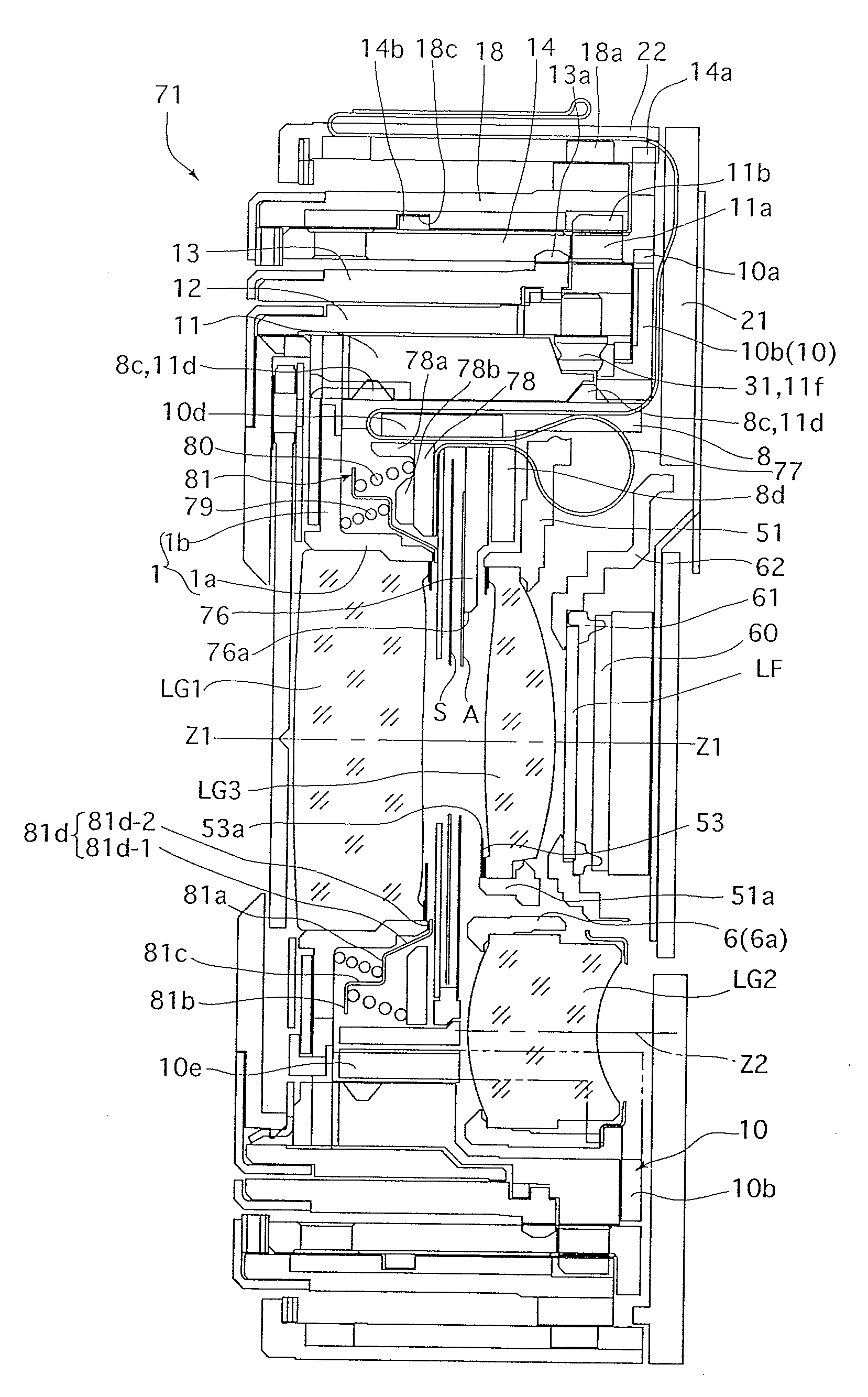
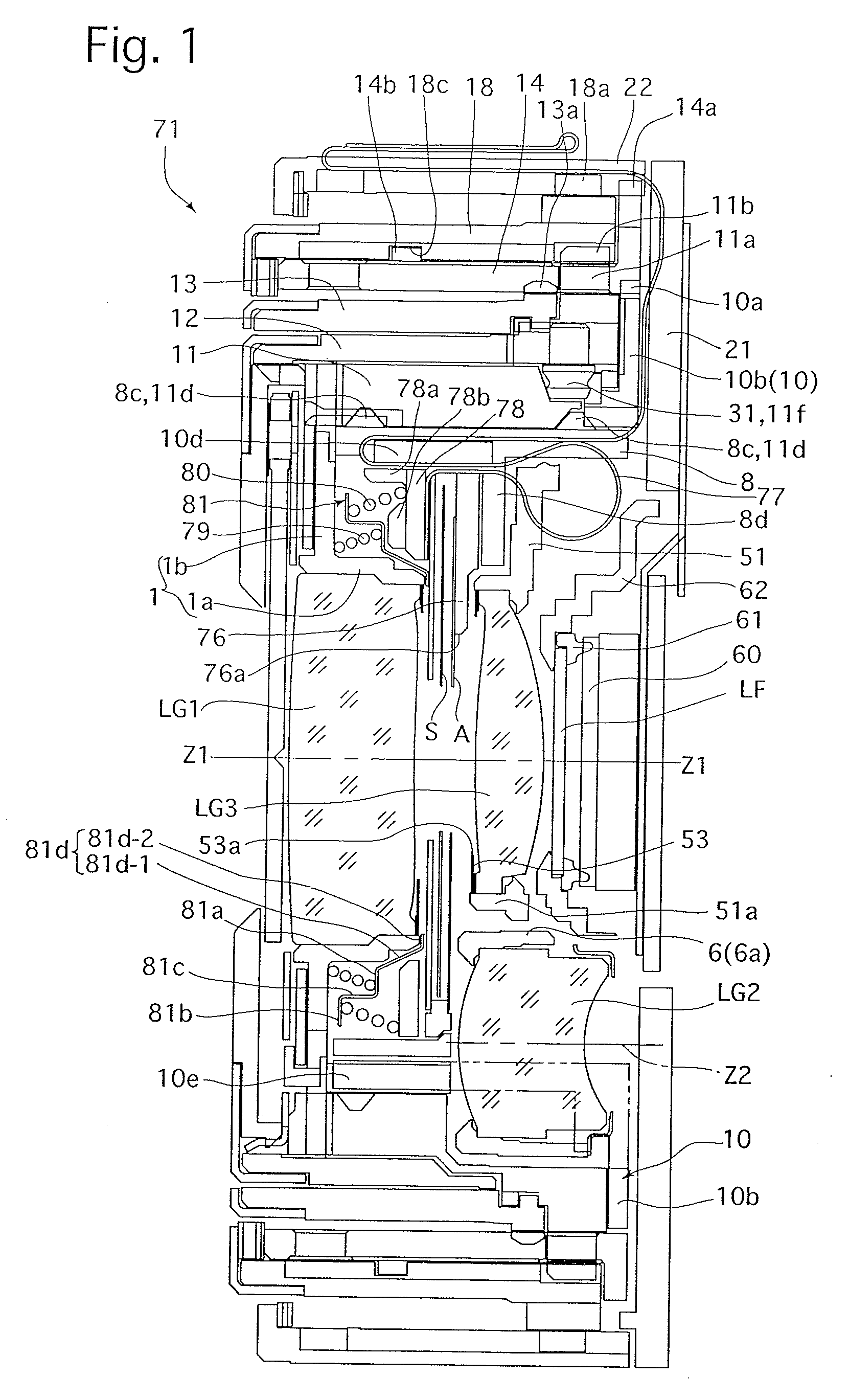
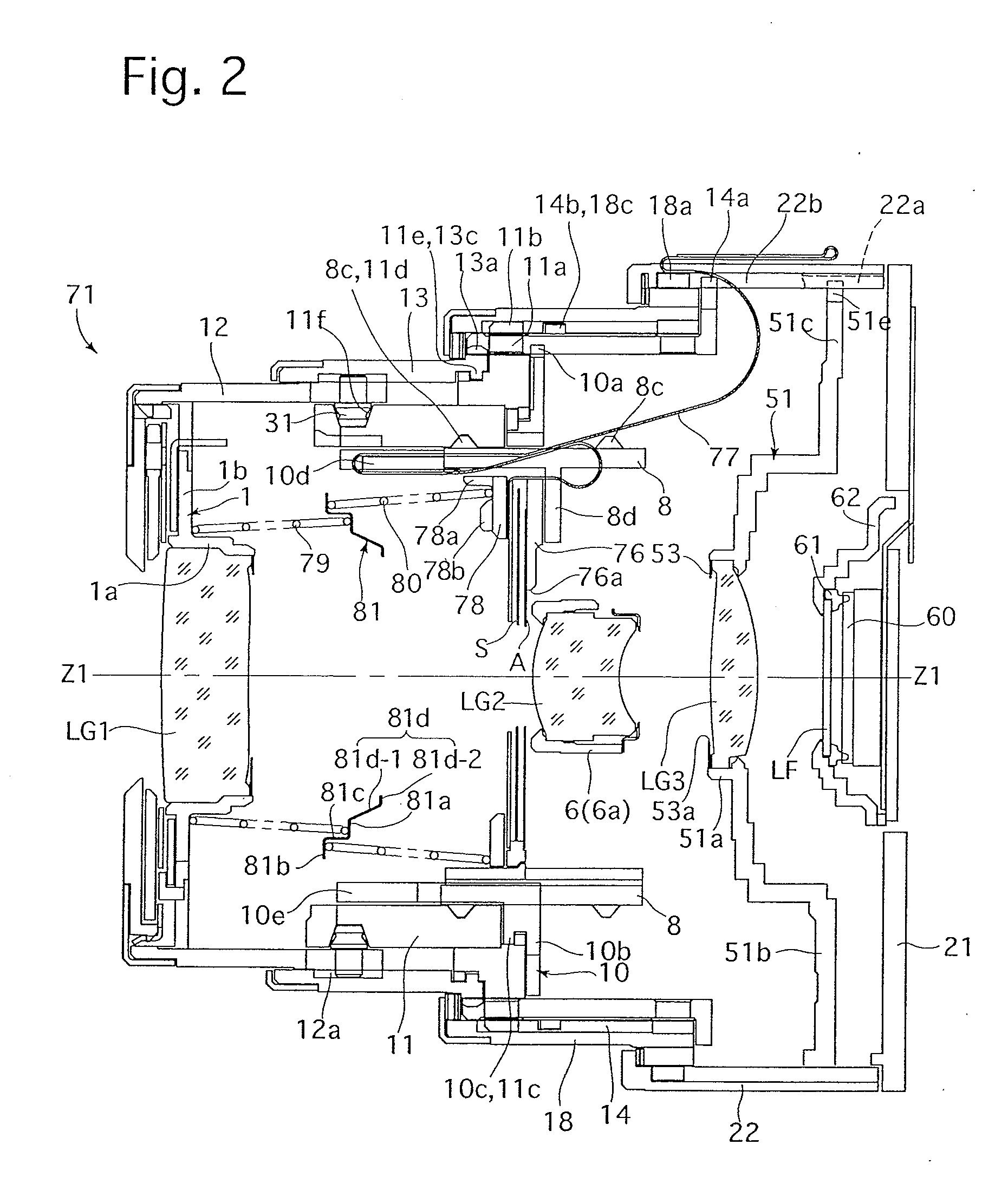
[0047]The overall structure of an embodiment of a zoom lens 71 will be first discussed hereinafter. The zoom lens 71 is provided with an imaging optical system (photographing optical system) including a first lens group LG1, a shutter S, an adjustable diaphragm A, a second lens group LG2, a third lens group LG3, a low-pass filter (optical filter) LF, and a solid-state image pickup device (hereinafter referred to as an image sensor) 60 in that order from the object side. An imaging optical axis (photographing optical axis) Z1 of the imaging optical system is substantially coincident with the central axis of each external barrel (12, 13 and 18) which forms the outward appearance of the zoom lens 71. The first lens group LG1 and the second lens group LG2 are driven along the imaging optical axis Z1 in a predetermined moving manner to perform a zooming operation, while the third lens group L3 is driven along the imaging optical axis Z1 to perform a focusing operation. In the following d...


PUM


Abstract

A light shielding structure of an optical device, includes a plurality of optical elements arranged at different positions in an optical axis direction. The light shielding structure includes at least one annular light shielding member positioned between two of the optical elements to shield harmful light, and a plurality of springs held between the two optical elements to be resiliently deformable in the optical axis direction. The springs include at least two springs, one of which is held between one of the two optical elements and the annular light shielding member while the other of the two springs is held between the other of the two optical elements and the annular light shielding member. The annular light shielding member is supported between the two optical elements in a balanced state between the spring forces of the plurality of springs.

Description

BACKGROUND OF THE INVENTION[0001]1. Field of the Invention[0002]The present invention relates to a light shielding structure of an optical device.[0003]2. Description of the Related Art[0004]In optical devices (e.g., lens barrels) composed of a collection of annular members, various light shielding structures for preventing harmful light such as stray light from entering inside the optical device through gaps formed between the annular members are used. Such light shielding structures conventionally have a general structure in which the entry pathway of harmful light is specified and in which at least one light shielding member (ring) is fixedly installed in the specified entry pathway, such as disclosed in Japanese Unexamined Patent Publication No. 2000-121903 (Japanese Patent No. 4094747).[0005]However, to install the light shielding member fixedly in the specified entry pathway, a special fixing structure is required, so that an increase in number of elements and an increase in m...

Claims


Application Information

Patent Timeline
IPC IPC(8): G02B7/02
CPCG02B7/102G02B7/04G02B7/10G02B5/003G02B7/021
Inventor NOMURA, HIROSHISASAKI, TAKAMITSUISHIZUKA, KAZUNORISHIMIZU, KUNIHIKO
Owner HOYA CORP
Why Eureka
Try Eureka