Electronic Ballast For A Low-Pressure Discharge Lamp With A Micro-Controller

a low-pressure discharge and micro-controller technology, applied in the direction of instruments, light sources, electrical apparatus, etc., can solve the problems of poor preheating and ignition properties, and achieve the effect of avoiding unnecessary energy consumption and high voltag

Inactive Publication Date: 2009-08-27
OSRAM GMBH
View PDF13 Cites 5 Cited by
  • Summary
  • Abstract
  • Description
  • Claims
  • Application Information

AI Technical Summary

Benefits of technology

The present invention relates to an electronic ballast that can work alone or combined with a lighting fixture. It offers flexibility by allowing different base options such as E27 or B22d while providing protection against accidental use with regular power circuits. Additionally, it prevents excessive voltages and avoids unnecessary energy consumption caused by malfunctioning lamps or missed plugs.

Problems solved by technology

The technical problem addressed in this patent text is the poor preheating and ignition properties of previous circuits of electronic ballasts used in low-voltage and DC systems, such as in automobiles, vessels, and the camping sector. These previous circuits use a freely oscillating push-pull converter or single transistor solutions, which have complex designs and require a relay for controlling the preheating and ignition phase.

Method used


Image

  • Electronic Ballast For A Low-Pressure Discharge Lamp With A Micro-Controller
  • Electronic Ballast For A Low-Pressure Discharge Lamp With A Micro-Controller
  • Electronic Ballast For A Low-Pressure Discharge Lamp With A Micro-Controller

Examples


Embodiment Construction

[0003]The object of the present invention is to improve an electronic ballast of the type described above in accordance with the precharacterizing clause of patent claim 1 in such a way that it responds in a flexible manner to various situations and nevertheless has a compact design.

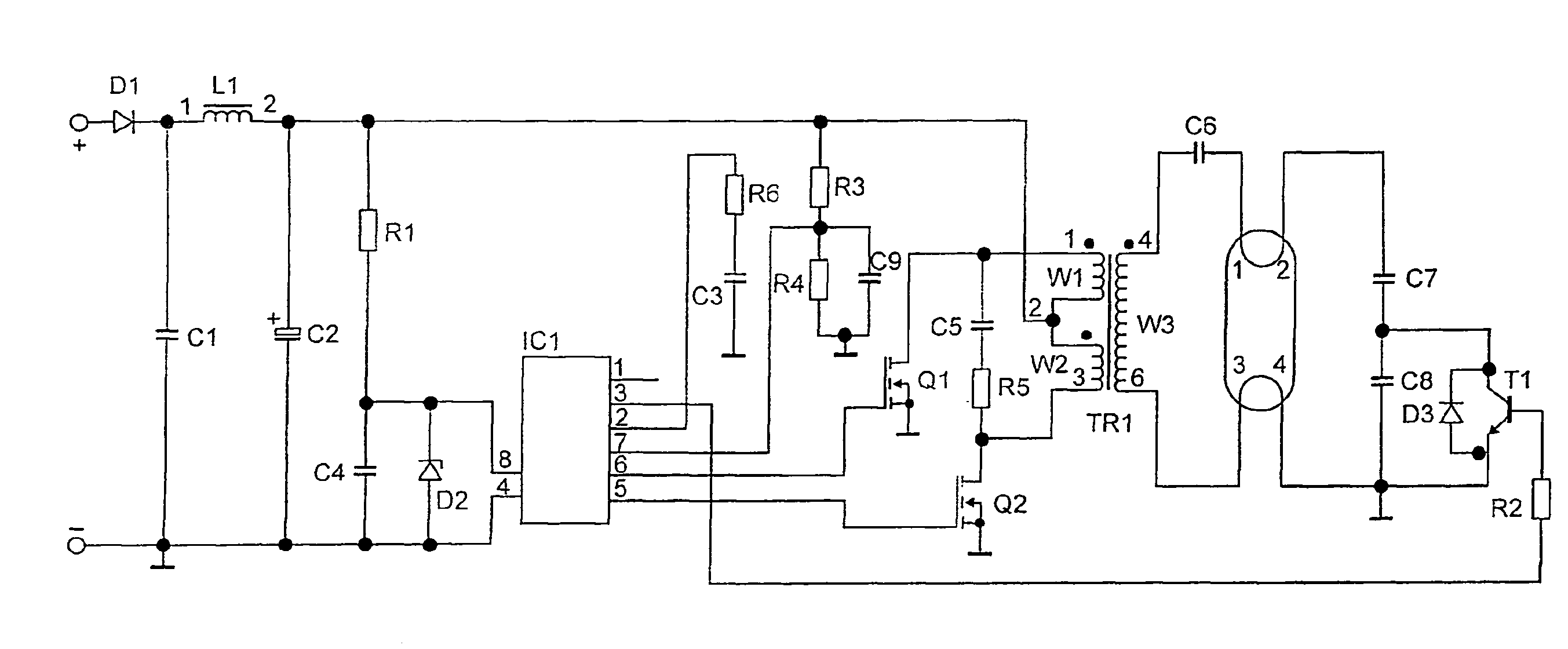
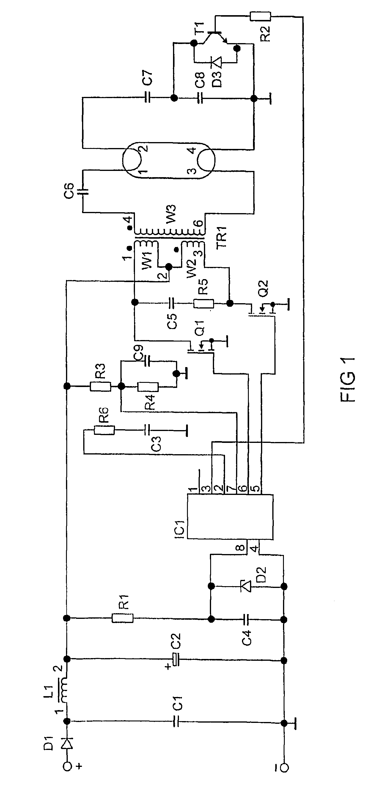
[0004]This object is achieved by virtue of the fact that a microcontroller drives the electronic switching element.

[0005]A microcontroller allows for flexible driving of the electronic switching elements and therefore makes it possible to adapt to various situations which arise owing to the predetermined properties of the luminous means.

[0006]In accordance with the invention, the driving of the at least one electronic switching element can take place indirectly or directly, i.e. with a driver stage interposed or not.

[0007]The switching element may be a transistor, in particular a MOSFET. Particularly preferably, a logic level MOSFET is used because the input voltages of the logic level MOSFET allow the t...


PUM


Abstract

The invention relates to an electronic ballast for a lamp, supplied with electrical energy from a power source, different to the mains AC network, comprising at least one electronic switch element for conversion of the supplied electrical power. According to the invention, a microcontroller controls the electronic switch element.

Description


Claims


Application Information

Patent Timeline
Owner OSRAM GMBH
Why Eureka
Try Eureka