
Pixel interpolation apparatus and method

a technology of interpolation apparatus and interpolation method, which is applied in the direction of optical-mechanical scanning signal generators, instruments, television systems, etc., can solve the problem of not being able to detect the direction of inclination in the interpolation direction, and achieve the effect of correctly performing the interpolation of the edge direction

Inactive Publication Date: 2009-08-27
FUJITSU LTD
View PDF4 Cites 14 Cited by
  • Summary
  • Abstract
  • Description
  • Claims
  • Application Information

AI Technical Summary

Benefits of technology

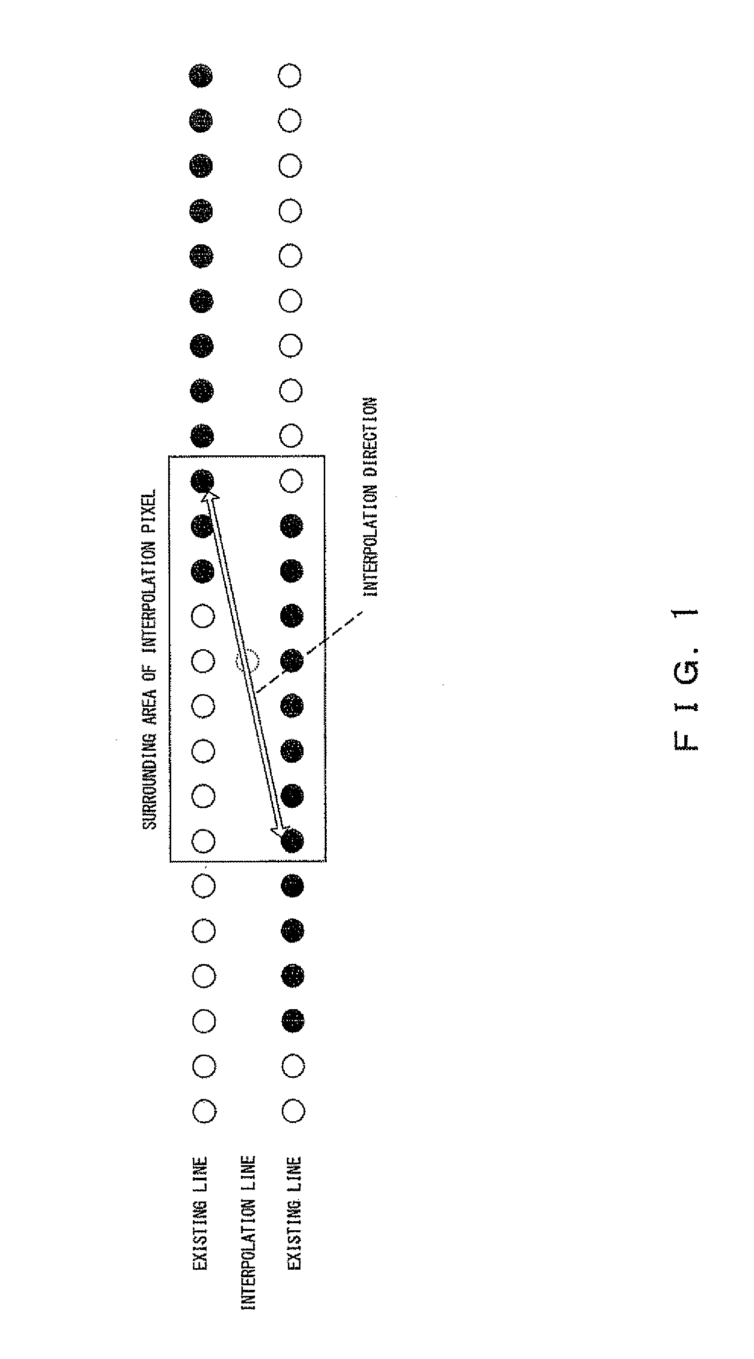
[0021]According to the disclosed pixel interpolation device, one set of continuous edges can be detected from pixels adjacent the interpolation pixel, an edge direction can be calculated on the basis of the detected one set of continuous edges and an interpolation pixel can be calculated. By calculating an edge direction from the combination of actually detected continuous edges without limiting a range for determining an edge direction, even the edge direction of a gently inclined edge can be correctly determined, thereby correctly performing the pixel interpolation of an edge direction.

Problems solved by technology

Specifically, if the width of the surrounding pixel area is small, the gently inclined interpolation direction cannot be detected.
Therefore, an edge direction for reducing jaggies is seldom interpolated, which is a problem.

Method used


Image

  • Pixel interpolation apparatus and method
  • Pixel interpolation apparatus and method
  • Pixel interpolation apparatus and method

Examples


Embodiment Construction

[0050]The preferred embodiments of the present invention are described in detail below with reference to the drawings.

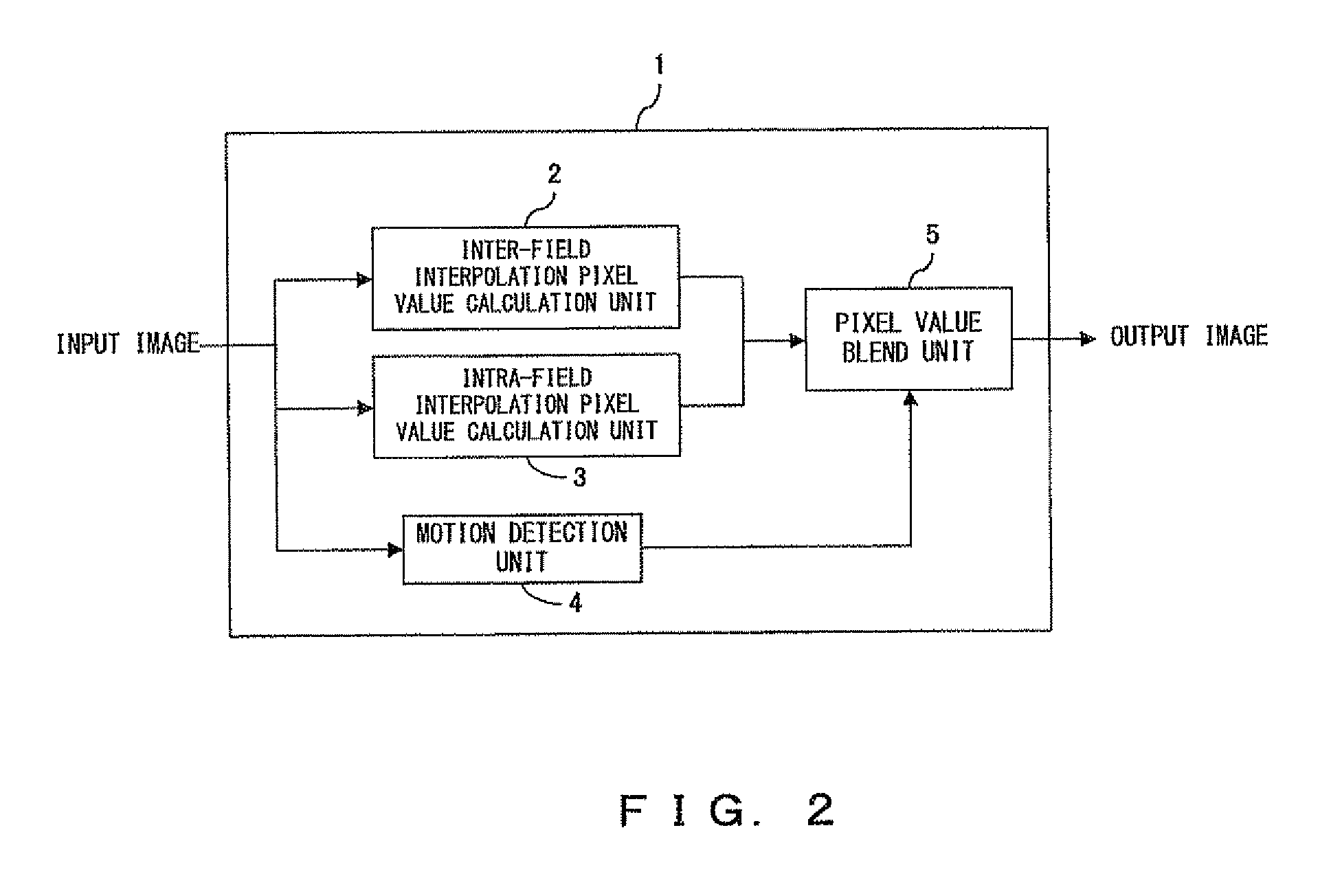
[0051]FIG. 2 shows the configuration of an interlace-progressive transform device. The interlace-progressive transform device 1 comprises an inter-field interpolation pixel value calculation unit 2, an intra-field interpolation pixel value calculation unit 3, a motion detection unit 4 and a pixel value blend unit 5.

[0052]Although a pixel interpolation method according to this preferred embodiment can also be applied to image enlargement, in the following description, pixel interpolation in interlace progressive transform is described as an example.

[0053]The inter-field interpolation pixel value calculation unit 2 detects the motion between two images in the field of the same parity, of inputted image signals, and calculates the interpolation pixel value of a field image of a different parity (this is called interpolation-target field image) between the two fields whe...


PUM


Abstract

In a pixel interpolation apparatus for interpolating pixels, an edge pixel detection unit detects edge pixels constituting an edge among pixels on lines positioned above / below the interpolation pixel. A continuous edge detection unit detects edge pixels in which two pixels or more consecutively line up among edge pixels detected by the edge pixel detection unit as a continuous edge. A continuous edge pair detection unit determines the combination of the continuous edges detected on each of the lines above and below the interpolation pixel among the continuous edges detected by the continuous edge detection unit. An edge direction determination unit determines the edge direction of the interpolation pixel on the basis of the positional relation of one set of continuous edges determined by the continuous edge pair detection unit. An interpolation pixel calculation unit calculates an interpolation pixel using the edge direction determined by the edge direction determination unit.

Description

BACKGROUND OF THE INVENTION [0001]1. Field of the Invention[0002]The present invention relates to a technique for interpolating pixels in a spatial direction by interlace progressive transform, image enlargement and the like.[0003]2. Description of the Related Art[0004]As examples of processes for interpolating pixels in the spatial direction, there are interlace progressive transform (progressive scan conversion), image enlargement and the like. Of these, in the interlace progressive transform, generally an interpolation pixel value is calculated by weighting and adding an intra-field interpolation pixel value obtained by intra-field interpolation and an inter-field interpolation pixel value obtained by inter-field interpolation according to the motion of a pixel. Alternatively, either the intra-field interpolation pixel value or the inter-field interpolation pixel value is selected.[0005]Since the pixels of each field exist only on every another line, generally bi-linear or bi-cub...

Claims


Application Information

Patent Timeline
Patent Type & Authority Applications(United States)
IPC IPC(8): G06K9/32G06K9/40
CPCG06K9/4609G06T3/403G06T3/4007G06V10/443
Inventor YAMADA, KOHJIHAMANO, TAKASHIIWASAKI, MARI
Owner FUJITSU LTD
Learn More