Centrifuges, in particular, for a lubricant oil in an internal combustion engine

Inactive Publication Date: 2009-08-27
HENGST WALTER
View PDF23 Cites 5 Cited by
  • Summary
  • Abstract
  • Description
  • Claims
  • Application Information

AI Technical Summary

Benefits of technology

[0014]Many internal combustion engines, in particular especially large engines, are often manufactured in relatively small piece counts, which has the consequence that only a correspondingly small number of centrifuges are required for them. For this case in particular, the present invention provides that the base is a component that is manufactured individually so as to be adapted to an associated device, in particular an internal combustion engine, and that can be assembled with different lids and/or with different rotors in various combinations to form different centrifuges. For example, here the base can be a sand casting that can be economically manufactured even in relatively small piece counts. Rotors and lids from the modular program can then be connected to this individually manufactured base, so that expensive special productions are not necessary for the rotors and lids.
[0015]In order in particular to achieve a simple installation of the centrifuges according to the present invention, it is preferably provided that the/each base have one or more connecting flanges that create a simultaneous mechanical and flow connection, for connection to an associated device, in particular an internal combustion engine, and/or for connection to another base. This ensures a simple and problem-free installation of the centrifuges, in which external conduits, which are expensive to attach and are liable to damage, are not required.
[0016]Finally, for the centrifuges ac

Problems solved by technology

Due to its size, such a rotor has to be made of metal, which means that the rotor is relatively heavy.
Moreover, due to the size and weight of the rotor containing the lubricant oil and deposited dirt, the bearing of the rotor is expensive.
Due to its size and its correspondingly high mass, despite the use of a large amount of lubricant oil for its drive the rotor nonetheless achieves only relatively l

Method used


Image

  • Centrifuges, in particular, for a lubricant oil in an internal combustion engine
  • Centrifuges, in particular, for a lubricant oil in an internal combustion engine
  • Centrifuges, in particular, for a lubricant oil in an internal combustion engine

Examples


Example

BRIEF DESCRIPTION OF THE DRAWINGS

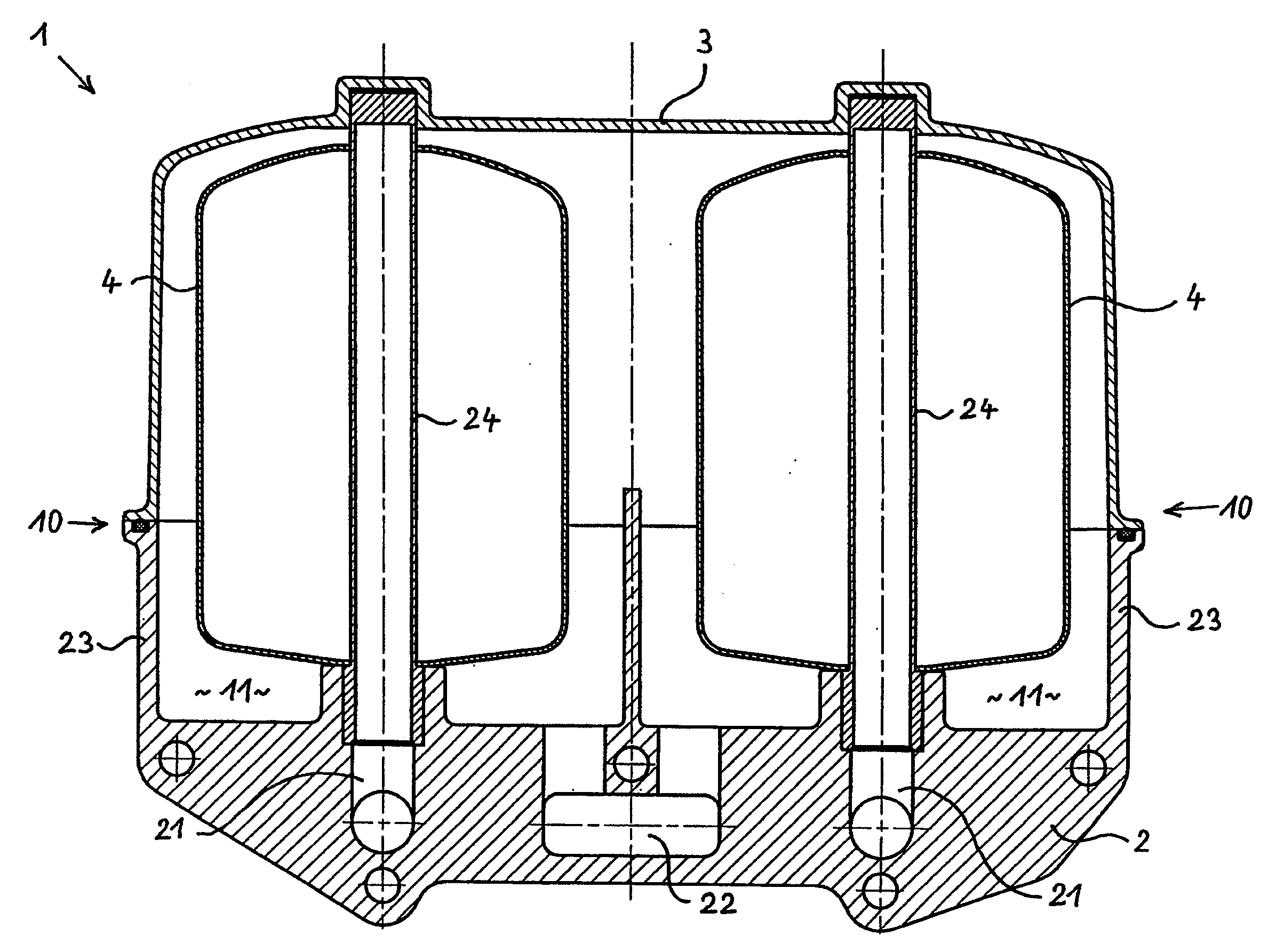
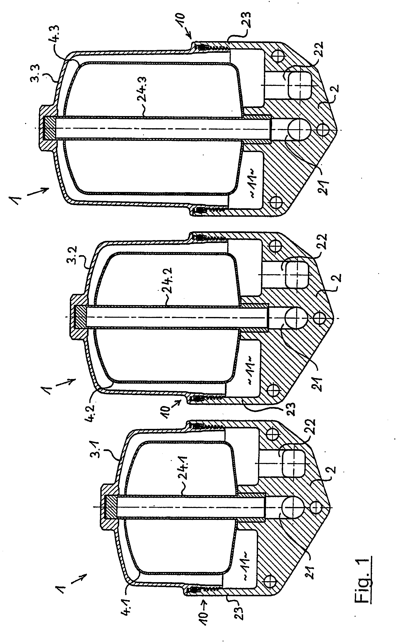
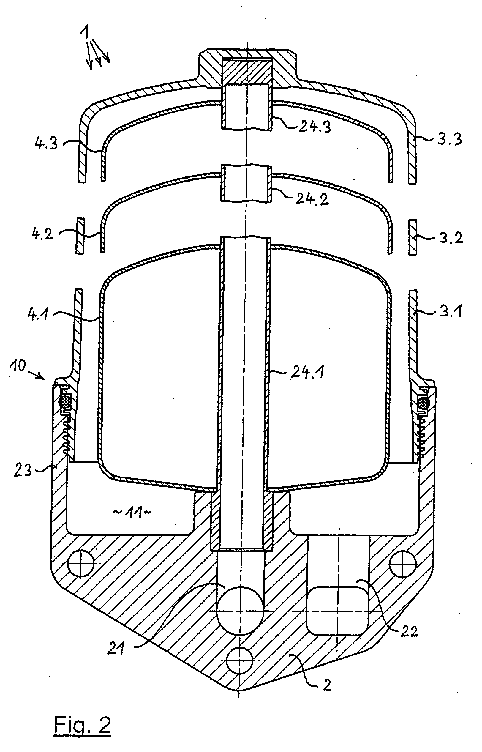
[0031]FIG. 1 shows three different centrifuges 1 alongside one another, for which it is characteristic that they have identical bases 2 each of which forms a lower housing part. Each base 2 comprises a supply channel 21 for a fluid that is to be cleaned in centrifuge 1, for example the lubricant oil of an associated internal combustion engine, as well as a drainage channel for carrying off the cleaned liquid from centrifuge 1. In addition, each base 2 comprises a peripheral wall 23 that extends upward. In each of the three centrifuges 1 shown in FIG. 1, a lid 3.1, 3.2, 3.3 is connected to peripheral wall 23; here, the lids are removably screwed on, with intermediate situation of a sealing ring. Lids 3.1 to 3.3 each have at the bottom an identical connecting end for connection to peripheral wall 23, but have heights that are different from one another, as is shown in FIG. 1.

[0032]In interior space 11 of each housing 10 formed by base 2 and the associa...


PUM


Abstract

Centrifuges, in particular for a lubricant oil in an internal combustion engine, are provided with a housing which comprises a base, a lid forming the second part of the housing and connectable to the base and a rotor arrangeable in the housing. Each centrifuge is embodied in the form of a modular unit which is assembled with the aid of modular system parts, wherein the modular system comprises different bases, and/or different lids and/or different rotors which can be assembled in the form of different combinations in such a way that different centrifuges are obtained.

Description

BACKGROUND OF THE INVENTION[0001]The present invention relates to centrifuges, in particular for the lubricant oil of an internal combustion engine, having a housing that comprises a base that forms a first housing part and a lid that is connectable to the base and that forms a second housing part, and having a rotor situated in the housing.[0002]Centrifuges of the type named above have long been used and are generally known due to their wide distribution, including use for the lubricant oil of an internal combustion engine. In this use, centrifuges are used to separate out fine particles of dirt that are carried along in the lubricant oil of the internal combustion engine. Here it is standard for the centrifuge to be situated in a bypass flow of the lubricant oil circuit of the internal combustion engine, while in the main flow of the lubricant oil circuit a lubricant oil filter having an exchangeable filter insert is standardly present. In internal combustion engines, in particula...

Claims


Application Information

Patent Timeline
IPC IPC(8): B04B11/06
CPCB04B5/005B04B5/10B04B7/02F01M2001/1057F01M11/03F01M2001/1035B04B7/08B04B5/00
Inventor BAUMANN, DIETER
Owner HENGST WALTER
Why Eureka
Try Eureka